The compound shaft shown in Fig. is attached to rigid supports. For the bronze segment AB, the diameter is 75 mm, t < 60 MPa, and G = 35 GPa. For the steel segment BC, the diameter is 50 mm, T< 80 MPa, and G = 83 GPa. If a = 2 m andb = 1.5 m, compute %3D the maximum torque T that can be applied. b A B
The compound shaft shown in Fig. is attached to rigid supports. For the bronze segment AB, the diameter is 75 mm, t < 60 MPa, and G = 35 GPa. For the steel segment BC, the diameter is 50 mm, T< 80 MPa, and G = 83 GPa. If a = 2 m andb = 1.5 m, compute %3D the maximum torque T that can be applied. b A B

Steel Design (Activate Learning with these NEW titles from Engineering!)
6th Edition
ISBN:9781337094740
Author:Segui, William T.
Publisher:Segui, William T.
Chapter10: Plate Girders
Section: Chapter Questions
Problem 10.7.8P

Related questions

Question
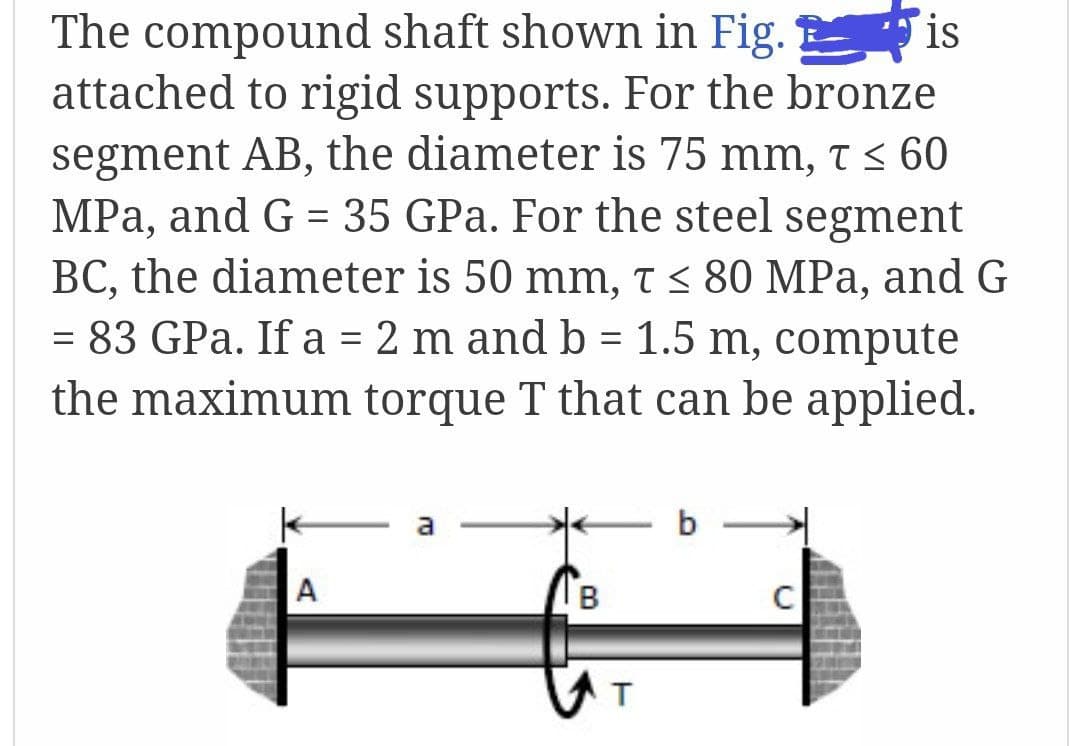
Transcribed Image Text:The compound shaft shown in Fig. is
attached to rigid supports. For the bronze
segment AB, the diameter is 75 mm, t < 60
MPa, and G = 35 GPa. For the steel segment
BC, the diameter is 50 mm, t < 80 MPa, and G
= 83 GPa. If a = 2 m and b = 1.5 m, compute
%3D
the maximum torque T that can be applied.
b
A
B
Expert Solution
This question has been solved!
Explore an expertly crafted, step-by-step solution for a thorough understanding of key concepts.

Step by step
Solved in 3 steps with 3 images

Knowledge Booster


Learn more about
Need a deep-dive on the concept behind this application? Look no further. Learn more about this topic, civil-engineering and related others by exploring similar questions and additional content below.Recommended textbooks for you
Steel Design (Activate Learning with these NEW ti…
Civil Engineering
ISBN:
9781337094740
Author:
Segui, William T.
Publisher:
Cengage Learning
Steel Design (Activate Learning with these NEW ti…
Civil Engineering
ISBN:
9781337094740
Author:
Segui, William T.
Publisher:
Cengage Learning