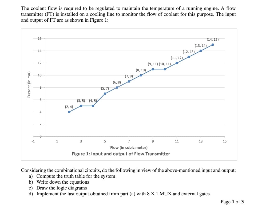
The coolant flow is required to be regulated to maintain the temperature of a running engine. A flow transmitter (FT) is installed on a cooling line to monitor the flow of coolant for this purpose. The input and output of FT are as shown in Figure 1: 16 (14, 15) (13, 14), 14 (12, 13) (11, 12) 12 (9, 11) (10, 11). (8, 10) 10 (7, 9) (6, 8) 8 (5, 7) 6 (3, 5) (4, 5) (2, 4) 4 2 -1 1 3 11 13 15 Flow (in cubic meter) Figure 1: Input and output of Flow Transmitter Considering the combinational circuits, do the following in view of the above-mentioned input and output: a) Compute the truth table for the system b) Write down the equations c) Draw the logic diagrams d) Implement the last output obtained from part (a) with 8 X 1 MUX and external gates Current (in mA)
The coolant flow is required to be regulated to maintain the temperature of a running engine. A flow transmitter (FT) is installed on a cooling line to monitor the flow of coolant for this purpose. The input and output of FT are as shown in Figure 1: 16 (14, 15) (13, 14), 14 (12, 13) (11, 12) 12 (9, 11) (10, 11). (8, 10) 10 (7, 9) (6, 8) 8 (5, 7) 6 (3, 5) (4, 5) (2, 4) 4 2 -1 1 3 11 13 15 Flow (in cubic meter) Figure 1: Input and output of Flow Transmitter Considering the combinational circuits, do the following in view of the above-mentioned input and output: a) Compute the truth table for the system b) Write down the equations c) Draw the logic diagrams d) Implement the last output obtained from part (a) with 8 X 1 MUX and external gates Current (in mA)

Operations Research : Applications and Algorithms
4th Edition
ISBN:9780534380588
Author:Wayne L. Winston
Publisher:Wayne L. Winston
Chapter9: Integer Programming
Section9.6: Solving Combinatorial Optimization Problems By The Branch-and-bound Method
Problem 4P

Related questions
Question
100%
subject DLD
plzz solve urgent with complete detail ..
thanks...
Transcribed Image Text:The coolant flow is required to be regulated to maintain the temperature of a running engine. A flow
transmitter (FT) is installed on a cooling line to monitor the flow of coolant for this purpose. The input
and output of FT are as shown in Figure 1:
16
(14, 15)
(13, 14),
14
(12, 13)
(11, 12),
12
(9, 11) (10, 11)
(8, 10)
10
(7, 9)
(6, 8)
(5, 7)
6
(3, 5) (4, 5),
(2, 4)
4
-1
1
3
5
9.
11
13
15
Flow (in cubic meter)
Figure 1: Input and output of Flow Transmitter
Considering the combinational circuits, do the following in view of the above-mentioned input and output:
a) Compute the truth table for the system
b) Write down the equations
c) Draw the logic diagrams
d) Implement the last output obtained from part (a) with 8 X 1 MUX and external gates
Page 1 of 3
Current (in mA)
Expert Solution
This question has been solved!
Explore an expertly crafted, step-by-step solution for a thorough understanding of key concepts.

Step by step
Solved in 4 steps with 3 images

Knowledge Booster


Learn more about
Need a deep-dive on the concept behind this application? Look no further. Learn more about this topic, computer-science and related others by exploring similar questions and additional content below.Recommended textbooks for you
Operations Research : Applications and Algorithms
Computer Science
ISBN:
9780534380588
Author:
Wayne L. Winston
Publisher:
Brooks Cole

Systems Architecture
Computer Science
ISBN:
9781305080195
Author:
Stephen D. Burd
Publisher:
Cengage Learning
Operations Research : Applications and Algorithms
Computer Science
ISBN:
9780534380588
Author:
Wayne L. Winston
Publisher:
Brooks Cole
Systems Architecture
Computer Science
ISBN:
9781305080195
Author:
Stephen D. Burd
Publisher:
Cengage Learning