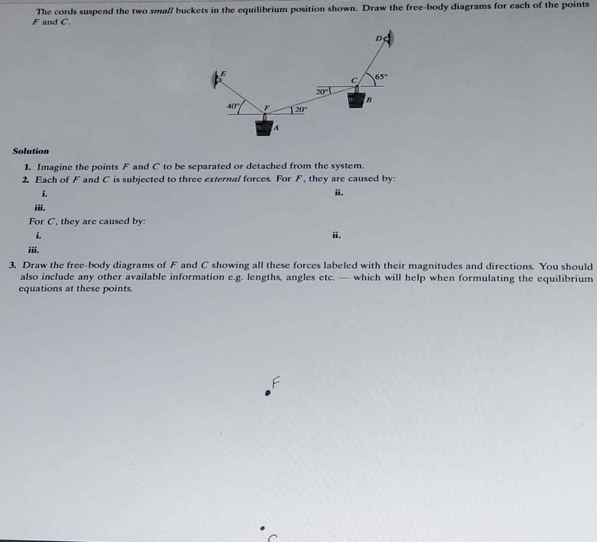
The cords suspend the two small buckets in the equilibrium position shown. Draw the free-body diagrams for each of the points F and C. 40° A 20° 20° B 65° Solution 1. Imagine the points F and C to be separated or detached from the system. 2. Each of F and C is subjected to three external forces. For F, they are caused by: i. ii. iii. For C, they are caused by: i. iii. 3. Draw the free-body diagrams of F and C showing all these forces labeled with their magnitudes and directions. You should also include any other available information e.g. lengths, angles etc. which will help when formulating the equilibrium equations at these points.
The cords suspend the two small buckets in the equilibrium position shown. Draw the free-body diagrams for each of the points F and C. 40° A 20° 20° B 65° Solution 1. Imagine the points F and C to be separated or detached from the system. 2. Each of F and C is subjected to three external forces. For F, they are caused by: i. ii. iii. For C, they are caused by: i. iii. 3. Draw the free-body diagrams of F and C showing all these forces labeled with their magnitudes and directions. You should also include any other available information e.g. lengths, angles etc. which will help when formulating the equilibrium equations at these points.

International Edition---engineering Mechanics: Statics, 4th Edition
4th Edition
ISBN:9781305501607
Author:Andrew Pytel And Jaan Kiusalaas
Publisher:Andrew Pytel And Jaan Kiusalaas
Chapter6: Beams And Cables
Section: Chapter Questions
Problem 6.73P: The cable of mass 1.8 kg/m is attached to a rigid support at A and passes over a smooth pulley at B....

Related questions

Question
Please help
Transcribed Image Text:The cords suspend the two small buckets in the equilibrium position shown. Draw the free-body diagrams for each of the points
F and C.
E
40%
HITRA
20°
20°
B
65°
Solution
1. Imagine the points F and C to be separated or detached from the system.
2. Each of F and C is subjected to three external forces. For F, they are caused by:
i.
ii.
iii.
For C, they are caused by:
i.
iii.
3. Draw the free-body diagrams of F and C showing all these forces labeled with their magnitudes and directions. You should
also include any other available information e.g. lengths, angles etc. - which will help when formulating the equilibrium
equations at these points.
Expert Solution
This question has been solved!
Explore an expertly crafted, step-by-step solution for a thorough understanding of key concepts.

This is a popular solution!

Trending now
This is a popular solution!

Step by step
Solved in 4 steps with 6 images

Knowledge Booster


Learn more about
Need a deep-dive on the concept behind this application? Look no further. Learn more about this topic, mechanical-engineering and related others by exploring similar questions and additional content below.Recommended textbooks for you
International Edition---engineering Mechanics: St…
Mechanical Engineering
ISBN:
9781305501607
Author:
Andrew Pytel And Jaan Kiusalaas
Publisher:
CENGAGE L
International Edition---engineering Mechanics: St…
Mechanical Engineering
ISBN:
9781305501607
Author:
Andrew Pytel And Jaan Kiusalaas
Publisher:
CENGAGE L