The critical load of the column is determined. In the case considered, the column is divided into two equal parts, joined by a torsional spring.You Are asked to analyze a similar system. This time, the upper section is one quarter of the column length, and the lower section is three quarters of the column length.a.What is the critical load?
The critical load of the column is determined. In the case considered, the column is divided into two equal parts, joined by a torsional spring.You Are asked to analyze a similar system. This time, the upper section is one quarter of the column length, and the lower section is three quarters of the column length.a.What is the critical load?

Elements Of Electromagnetics
7th Edition
ISBN:9780190698614
Author:Sadiku, Matthew N. O.
Publisher:Sadiku, Matthew N. O.
ChapterMA: Math Assessment
Section: Chapter Questions
Problem 1.1MA

Related questions
Question
Page 692 to 694.In these pages,the problem of Fig.10.3 is analyzed.The critical load of the column is determined. In the case considered, the column is divided into two equal parts, joined by a torsional spring.You Are asked to analyze a similar system. This time, the upper section is one quarter of the column length, and the lower section is three quarters of the column length.a.What is the critical load?b.Briefly give your thoughts regarding comparison of the answer in the book and your answer
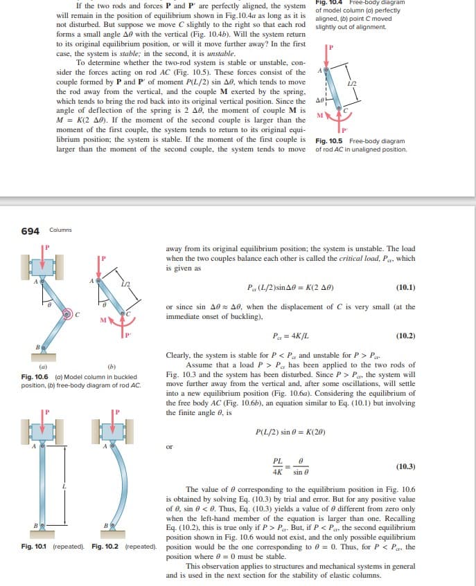
Transcribed Image Text:If the two rods and forces P and P' are perfectly aligned, the system
will remain in the position of equilibrium shown in Fig.10.4a as long as it is
not disturbed. But suppose we move C slightly to the right so that each rod
forms a small angle A0 with the vertical (Fig. 10.4b). Will the system return
to its original equilibrium position, or will it move further away? In the first
case, the system is stable; in the second, it is unstable.
To determine whether the two-rod system is stable or unstable, con-
sider the forces acting on rod AC (Fig. 10.5). These forces consist of the
couple formed by P and P' of moment P(L/2) sin A0, which tends to move
the rod away from the vertical, and the couple M exerted by the spring,
which tends to bring the rod back into its original vertical position. Since the
angle of deflection of the spring is 2 A0, the moment of couple M is
M = K(2 A0). If the moment of the second couple is larger than the
moment of the first couple, the system tends to return to its original equi-
librium position; the system is stable. If the moment of the first couple is
larger than the moment of the second couple, the system tends to move
694 Columns
Be
(a)
(b)
Fig. 10.6 (0) Model column in buckled
position, (b) free-body diagram of rod AC.
B
Fig. 10.4 Free-body diagram
of model column (a) perfectly
aligned, (b) point C moved
slightly out of alignment.
A
or
A0
M
PL
0
4K sin 8
away from its original equilibrium position; the system is unstable. The load
when the two couples balance each other is called the critical load, Pa, which
is given as
1/2
Fig. 10.5 Free-body diagram
of rod AC in unaligned position.
Par (L/2)sin A0 = K(2 A0)
(10.1)
or since sin A0 A0, when the displacement of C is very small (at the
immediate onset of buckling),
P₁ = 4K/L
Clearly, the system is stable for P < P and unstable for P> Par
Assume that a load P > Per has been applied to the two rods of
Fig. 10.3 and the system has been disturbed. Since P> Per, the system will
move further away from the vertical and, after some oscillations, will settle
into a new equilibrium position (Fig. 10.6a). Considering the equilibrium of
the free body AC (Fig. 10.6b), an equation similar to Eq. (10.1) but involving
the finite angle 8, is
P(L/2) sin = K(20)
(10.2)
(10.3)
The value of corresponding to the equilibrium position in Fig. 10.6
is obtained by solving Eq. (10.3) by trial and error. But for any positive value
of 0, sin 0 <0. Thus, Eq. (10.3) yields a value of 0 different from zero only
when the left-hand member of the equation is larger than one. Recalling
Eq. (10.2), this is true only if P> P. But, if P < Pa, the second equilibrium
position shown in Fig. 10.6 would not exist, and the only possible equilibrium
Fig. 10.1 (repeated). Fig. 10.2 (repeated). position would be the one corresponding to 0 = 0. Thus, for P < Pa, the
position where 0 = 0 must be stable.
This observation applies to structures and mechanical systems in general
and is used in the next section for the stability of elastic columns.
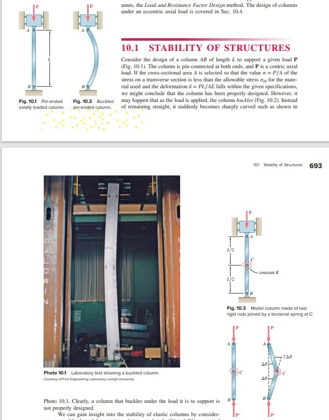
Transcribed Image Text:B
Fig. 10.1 Pin-ended Fig. 10.2 Buckled
axially loaded column. pin-ended column.
->
umns, the Load and Resistance Factor Design method. The design of columns
under an eccentric axial load is covered in Sec. 10.4.
10.1
STABILITY OF STRUCTURES
Consider the design of a column AB of length L to support a given load P
(Fig. 10.1). The column is pin-connected at both ends, and P is a centric axial
load. If the cross-sectional area A is selected so that the value 6 = P/A of the
stress on a transverse section is less than the allowable stress all for the mate-
rial used and the deformation & PL/AE falls within the given specifications,
we might conclude that the column has been properly designed. However, it
may happen that as the load is applied, the column buckles (Fig. 10.2). Instead
of remaining straight, it suddenly becomes sharply curved such as shown in
Photo 10.1 Laboratory test showing a buckled column.
Courtesy of Fritz Engineering Laboratory, Lehigh University
Photo 10.1. Clearly, a column that buckles under the load it is to support is
not properly designed.
We can gain insight into the stability of elastic columns by consider-
L/2
L/2
AG
Be
10.1 Stability of Structures
Fig. 10.3 Model column made of two
rigid rods joined by a torsional spring at C.
P
- constant K
ΔΘ
AB
B
240
693
с
Expert Solution
This question has been solved!
Explore an expertly crafted, step-by-step solution for a thorough understanding of key concepts.

This is a popular solution!

Trending now
This is a popular solution!

Step by step
Solved in 4 steps with 3 images

Knowledge Booster


Learn more about
Need a deep-dive on the concept behind this application? Look no further. Learn more about this topic, mechanical-engineering and related others by exploring similar questions and additional content below.Recommended textbooks for you
Elements Of Electromagnetics
Mechanical Engineering
ISBN:
9780190698614
Author:
Sadiku, Matthew N. O.
Publisher:
Oxford University Press

Mechanics of Materials (10th Edition)
Mechanical Engineering
ISBN:
9780134319650
Author:
Russell C. Hibbeler
Publisher:
PEARSON

Thermodynamics: An Engineering Approach
Mechanical Engineering
ISBN:
9781259822674
Author:
Yunus A. Cengel Dr., Michael A. Boles
Publisher:
McGraw-Hill Education
Elements Of Electromagnetics
Mechanical Engineering
ISBN:
9780190698614
Author:
Sadiku, Matthew N. O.
Publisher:
Oxford University Press
Mechanics of Materials (10th Edition)
Mechanical Engineering
ISBN:
9780134319650
Author:
Russell C. Hibbeler
Publisher:
PEARSON
Thermodynamics: An Engineering Approach
Mechanical Engineering
ISBN:
9781259822674
Author:
Yunus A. Cengel Dr., Michael A. Boles
Publisher:
McGraw-Hill Education

Control Systems Engineering
Mechanical Engineering
ISBN:
9781118170519
Author:
Norman S. Nise
Publisher:
WILEY

Mechanics of Materials (MindTap Course List)
Mechanical Engineering
ISBN:
9781337093347
Author:
Barry J. Goodno, James M. Gere
Publisher:
Cengage Learning

Engineering Mechanics: Statics
Mechanical Engineering
ISBN:
9781118807330
Author:
James L. Meriam, L. G. Kraige, J. N. Bolton
Publisher:
WILEY