The dimensions of a Francis radial-flow hydroturbine are r2 = 2.00 m, r1 = 1.30 m, b2 = 0.85 m, and b1 = 2.10 m, where location 2 is the inlet and location 1 is the outlet. At the turbine inlet and outflow, the runner blade angles are β2 = 71.4° and β1 = 15.3°, respectively. The runner rotates at a rate of ń = 160 rpm. At design conditions, the volume flow rate is 80.0 m3 /s. (a) State the necessary assumptions and calculate the angle α2 at which the wicket gates should turn the flow (Figure Q1), with α2 measured from the radial direction at the runner inlet. (b) Calculate the swirl angle α1 (Figure Q1), where α1 is the angle measured from the radial direction at the runner output. (c) Calculate the needed net head and power output. (d) Discuss the actual power output and head required for actual case of the turbine (irreversibility not neglected). (Properties For water at 20oC, ρ = 998.0 kg/m3)


The dimensions of a Francis radial-flow hydroturbine are r2 = 2.00 m, r1 = 1.30 m, b2 = 0.85 m, and b1 = 2.10 m, where location 2 is the inlet and location 1 is the outlet. At the turbine inlet and outflow, the runner blade angles are β2 = 71.4° and β1 = 15.3°, respectively. The runner rotates at a rate of ń = 160 rpm. At design conditions, the volume flow rate is 80.0 m3 /s.
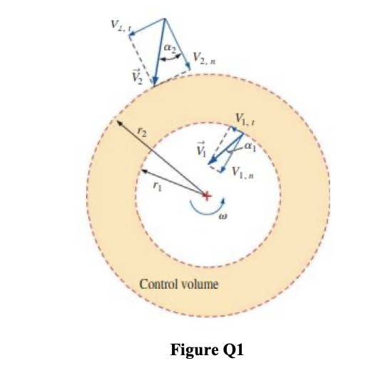
(a) State the necessary assumptions and calculate the angle α2 at which the wicket gates should turn the flow (Figure Q1), with α2 measured from the radial direction at the runner inlet.
(b) Calculate the swirl angle α1 (Figure Q1), where α1 is the angle measured from the radial direction at the runner output.
(c) Calculate the needed net head and power output.
(d) Discuss the actual power output and head required for actual case of the turbine (irreversibility not neglected).
(Properties For water at 20oC, ρ = 998.0 kg/m3)


Trending now
This is a popular solution!

Step by step
Solved in 4 steps with 4 images


