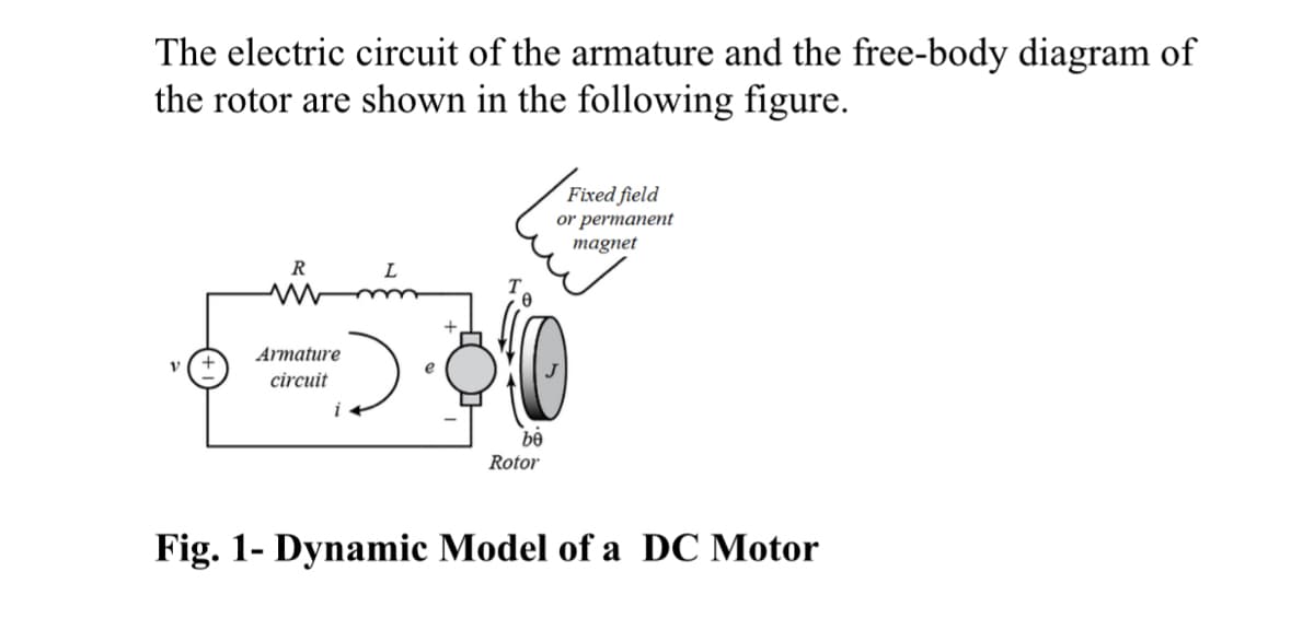
The electric circuit of the armature and the free-body diagram of the rotor are shown in the following figure. R Armature circuit L be Rotor Fixed field or permanent magnet Fig. 1- Dynamic Model of a DC Motor
The electric circuit of the armature and the free-body diagram of the rotor are shown in the following figure. R Armature circuit L be Rotor Fixed field or permanent magnet Fig. 1- Dynamic Model of a DC Motor

Introductory Circuit Analysis (13th Edition)
13th Edition
ISBN:9780133923605
Author:Robert L. Boylestad
Publisher:Robert L. Boylestad
Chapter1: Introduction
Section: Chapter Questions
Problem 1P: Visit your local library (at school or home) and describe the extent to which it provides literature...

Related questions

Question
100%
Please answer questions and label the answers to the right question
Transcribed Image Text:The electric circuit of the armature and the free-body diagram of
the rotor are shown in the following figure.
R
ww
Armature
circuit
L
30
be
Rotor
Fig. 1- Dynamic Model of a DC Motor
i
Fixed field
or permanent
magnet
Transcribed Image Text:PART I. Writing the equations that describe the behavior of a
DC motor
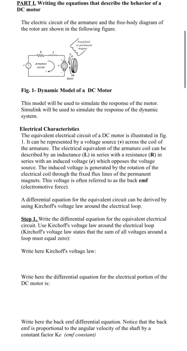
The electric circuit of the armature and the free-body diagram of
the rotor are shown in the following figure.
Armature
circuit
Rotor
Fixed field
or permanent
magnet
Fig. 1- Dynamic Model of a DC Motor
This model will be used to simulate the response of the motor.
Simulink will be used to simulate the response of the dynamic
system.
Electrical Characteristics
The equivalent electrical circuit of a DC motor is illustrated in fig.
1. It can be represented by a voltage source (v) across the coil of
the armature. The electrical equivalent of the armature coil can be
described by an inductance (L) in series with a resistance (R) in
series with an induced voltage (e) which opposes the voltage
source. The induced voltage is generated by the rotation of the
electrical coil through the fixed flux lines of the permanent
magnets. This voltage is often referred to as the back emf
(electromotive force).
A differential equation for the equivalent circuit can be derived by
using Kirchoff's voltage law around the electrical loop.
Step 1. Write the differential equation for the equivalent electrical
circuit. Use Kirchoff's voltage law around the electrical loop
(Kirchoff's voltage law states that the sum of all voltages around a
loop must equal zero):
Write here Kirchoff's voltage law:
Write here the differential equation for the electrical portion of the
DC motor is:
Write here the back emf differential equation. Notice that the back
emf is proportional to the angular velocity of the shaft by a
constant factor Ke (emf constant)
Expert Solution
This question has been solved!
Explore an expertly crafted, step-by-step solution for a thorough understanding of key concepts.

Step by step
Solved in 5 steps with 18 images

Knowledge Booster


Learn more about
Need a deep-dive on the concept behind this application? Look no further. Learn more about this topic, electrical-engineering and related others by exploring similar questions and additional content below.Recommended textbooks for you
Introductory Circuit Analysis (13th Edition)
Electrical Engineering
ISBN:
9780133923605
Author:
Robert L. Boylestad
Publisher:
PEARSON

Delmar's Standard Textbook Of Electricity
Electrical Engineering
ISBN:
9781337900348
Author:
Stephen L. Herman
Publisher:
Cengage Learning

Programmable Logic Controllers
Electrical Engineering
ISBN:
9780073373843
Author:
Frank D. Petruzella
Publisher:
McGraw-Hill Education
Introductory Circuit Analysis (13th Edition)
Electrical Engineering
ISBN:
9780133923605
Author:
Robert L. Boylestad
Publisher:
PEARSON
Delmar's Standard Textbook Of Electricity
Electrical Engineering
ISBN:
9781337900348
Author:
Stephen L. Herman
Publisher:
Cengage Learning
Programmable Logic Controllers
Electrical Engineering
ISBN:
9780073373843
Author:
Frank D. Petruzella
Publisher:
McGraw-Hill Education

Fundamentals of Electric Circuits
Electrical Engineering
ISBN:
9780078028229
Author:
Charles K Alexander, Matthew Sadiku
Publisher:
McGraw-Hill Education

Electric Circuits. (11th Edition)
Electrical Engineering
ISBN:
9780134746968
Author:
James W. Nilsson, Susan Riedel
Publisher:
PEARSON

Engineering Electromagnetics
Electrical Engineering
ISBN:
9780078028151
Author:
Hayt, William H. (william Hart), Jr, BUCK, John A.
Publisher:
Mcgraw-hill Education,