The figure belows shows three components of an air-conditioning system, where T3 = 95°F and m3 = 1.5 lb/s. Refrigerant 134a flows through a throttling valve and a heat exchanger while air flows through a fan and the same heat exchanger. Data for steady-state operation are given on the figure. There is no significant heat transfer between any of the components and the surroundings. Kinetic and potential energy effects are negligible. Saturated liquid R-134a T3, m3 Throttling valve lb/s P4= 60 lbf/in.² Air T₁ = 535°R Cp=0.240 Btu/lb-"R Fan wwwwww T₂=528°R 2 5 Wey=-0.2 hp Saturated vapor Ps= P4 -Heat exchanger Modeling air as an ideal gas with constant cp = 0.240 Btu/lb °R, determine the mass flow rate of the air, in lb/s. m₁ = i
The figure belows shows three components of an air-conditioning system, where T3 = 95°F and m3 = 1.5 lb/s. Refrigerant 134a flows through a throttling valve and a heat exchanger while air flows through a fan and the same heat exchanger. Data for steady-state operation are given on the figure. There is no significant heat transfer between any of the components and the surroundings. Kinetic and potential energy effects are negligible. Saturated liquid R-134a T3, m3 Throttling valve lb/s P4= 60 lbf/in.² Air T₁ = 535°R Cp=0.240 Btu/lb-"R Fan wwwwww T₂=528°R 2 5 Wey=-0.2 hp Saturated vapor Ps= P4 -Heat exchanger Modeling air as an ideal gas with constant cp = 0.240 Btu/lb °R, determine the mass flow rate of the air, in lb/s. m₁ = i

Chapter3: The First Law Of Thermodynamics
Section: Chapter Questions
Problem 97CP: The insulated cylinder shown below is closed at both ends and contains an insulating piston that is...

Related questions
Question
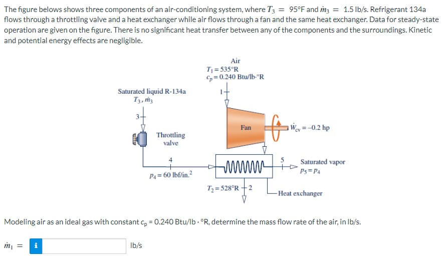
Transcribed Image Text:The figure belows shows three components of an air-conditioning system, where T3 = 95°F and m3 = 1.5 lb/s. Refrigerant 134a
flows through a throttling valve and a heat exchanger while air flows through a fan and the same heat exchanger. Data for steady-state
operation are given on the figure. There is no significant heat transfer between any of the components and the surroundings. Kinetic
and potential energy effects are negligible.
Saturated liquid R-134a
T3, m3
m₁ = i
Throttling
valve
lb/s
4
P4= 60 lbf/in.²
Air
T₁ = 535°R
Cp=0.240 Btu/lb-ºR
Fan
wwwwww
T₂=528°R +2
5
Wey = -0.2 hp
Saturated vapor
Ps= P4
Modeling air as an ideal gas with constant cp = 0.240 Btu/lb. °R, determine the mass flow rate of the air, in lb/s.
-Heat exchanger
Expert Solution
This question has been solved!
Explore an expertly crafted, step-by-step solution for a thorough understanding of key concepts.

Step by step
Solved in 4 steps with 4 images

Knowledge Booster


Learn more about
Need a deep-dive on the concept behind this application? Look no further. Learn more about this topic, physics and related others by exploring similar questions and additional content below.Recommended textbooks for you

Physics for Scientists and Engineers: Foundations…
Physics
ISBN:
9781133939146
Author:
Katz, Debora M.
Publisher:
Cengage Learning

Physics for Scientists and Engineers, Technology …
Physics
ISBN:
9781305116399
Author:
Raymond A. Serway, John W. Jewett
Publisher:
Cengage Learning
Physics for Scientists and Engineers: Foundations…
Physics
ISBN:
9781133939146
Author:
Katz, Debora M.
Publisher:
Cengage Learning
Physics for Scientists and Engineers, Technology …
Physics
ISBN:
9781305116399
Author:
Raymond A. Serway, John W. Jewett
Publisher:
Cengage Learning