The following figure illustrates the configuration of a two-bundle and completely transposed transmission line system operating at 50 Hz. The transmission line length is 100 km, and each bundle consists of conductors with a diameter of 6.0 mm. The resistance of each bundle is 0.12 92 per kilometer. Answer the following questions. a) The inductance in H/m for each phase of the transmission line. b) The total inductive reactance in 2 for each phase of the transmission line. c) The capacitance in F/m for each phase of the transmission line.
The following figure illustrates the configuration of a two-bundle and completely transposed transmission line system operating at 50 Hz. The transmission line length is 100 km, and each bundle consists of conductors with a diameter of 6.0 mm. The resistance of each bundle is 0.12 92 per kilometer. Answer the following questions. a) The inductance in H/m for each phase of the transmission line. b) The total inductive reactance in 2 for each phase of the transmission line. c) The capacitance in F/m for each phase of the transmission line.

Power System Analysis and Design (MindTap Course List)
6th Edition
ISBN:9781305632134
Author:J. Duncan Glover, Thomas Overbye, Mulukutla S. Sarma
Publisher:J. Duncan Glover, Thomas Overbye, Mulukutla S. Sarma
Chapter4: Transmission Line Parameters
Section: Chapter Questions
Problem 4.13P: A single-phase overhead transmission line consists of two solid aluminum conductors having a radius...

Related questions
Question
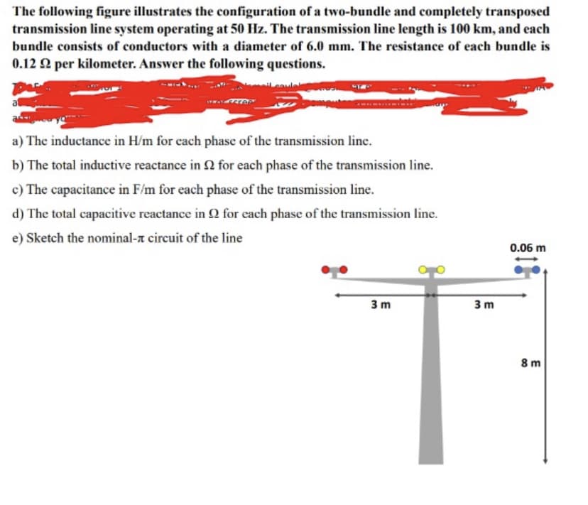
Transcribed Image Text:The following figure illustrates the configuration of a two-bundle and completely transposed
transmission line system operating at 50 Hz. The transmission line length is 100 km, and each
bundle consists of conductors with a diameter of 6.0 mm. The resistance of each bundle is
0.12 22 per kilometer. Answer the following questions.
a) The inductance in H/m for each phase of the transmission line.
b) The total inductive reactance in 2 for each phase of the transmission line.
c) The capacitance in F/m for each phase of the transmission line.
d) The total capacitive reactance in 92 for each phase of the transmission line.
e) Sketch the nominal- circuit of the line
3m
3m
0.06 m
8m
Expert Solution
This question has been solved!
Explore an expertly crafted, step-by-step solution for a thorough understanding of key concepts.

Step by step
Solved in 5 steps with 15 images

Knowledge Booster


Learn more about
Need a deep-dive on the concept behind this application? Look no further. Learn more about this topic, electrical-engineering and related others by exploring similar questions and additional content below.Recommended textbooks for you
Power System Analysis and Design (MindTap Course …
Electrical Engineering
ISBN:
9781305632134
Author:
J. Duncan Glover, Thomas Overbye, Mulukutla S. Sarma
Publisher:
Cengage Learning
Power System Analysis and Design (MindTap Course …
Electrical Engineering
ISBN:
9781305632134
Author:
J. Duncan Glover, Thomas Overbye, Mulukutla S. Sarma
Publisher:
Cengage Learning