the following static CMOS logic gate, where A, B, C, D are the logic gate inputs and O/P is the output: B-dQ6 c-d[Q7 C A - Q5 AQ1 D Ú B T Figure 1 D-d[Q8 Q4 Q3 Q2 VDD O/P Vss The logic gate from (a) needs to drive a capacitive load of 150 fF with a rise- time and fall-time of 0.5 ns. If the length of all transistors is 0.5 μm, calculate the required widths for all P-type and all N-type MOSFETS in your logic gate to achieve the required edge-speeds. Clearly show the calculation steps in your solution. Assume VDD = 5 V, K'n = 50 µA/V², K'p = 20 μA/V²
the following static CMOS logic gate, where A, B, C, D are the logic gate inputs and O/P is the output: B-dQ6 c-d[Q7 C A - Q5 AQ1 D Ú B T Figure 1 D-d[Q8 Q4 Q3 Q2 VDD O/P Vss The logic gate from (a) needs to drive a capacitive load of 150 fF with a rise- time and fall-time of 0.5 ns. If the length of all transistors is 0.5 μm, calculate the required widths for all P-type and all N-type MOSFETS in your logic gate to achieve the required edge-speeds. Clearly show the calculation steps in your solution. Assume VDD = 5 V, K'n = 50 µA/V², K'p = 20 μA/V²

Chapter22: Sequence Control
Section: Chapter Questions
Problem 6SQ: Draw a symbol for a solid-state logic element AND.

Related questions
Question
Please may you give the solution to this computer science question in a step by step form.
Thank you
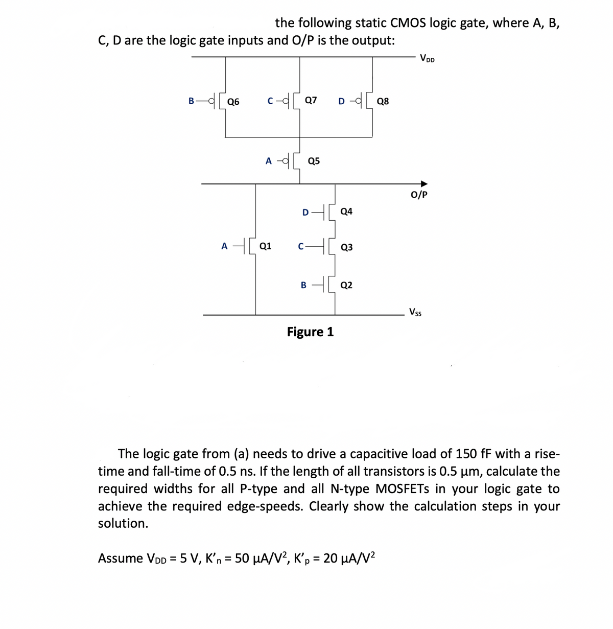
Transcribed Image Text:the following static CMOS logic gate, where A, B,
C, D are the logic gate inputs and O/P is the output:
B-q[Q6
A
c-d[Q7
A
Q1
-d[ Q5
D
Itɔ
B
D-Q8
Figure 1
Q4
Q3
40 Q2
VDD
O/P
Vss
The logic gate from (a) needs to drive a capacitive load of 150 ff with a rise-
time and fall-time of 0.5 ns. If the length of all transistors is 0.5 µm, calculate the
required widths for all P-type and all N-type MOSFETs in your logic gate to
achieve the required edge-speeds. Clearly show the calculation steps in your
solution.
Assume VDD = 5 V, K'n = 50 μA/V², K'p = 20 μA/V²
Expert Solution
This question has been solved!
Explore an expertly crafted, step-by-step solution for a thorough understanding of key concepts.

Step by step
Solved in 3 steps with 7 images

Knowledge Booster


Learn more about
Need a deep-dive on the concept behind this application? Look no further. Learn more about this topic, electrical-engineering and related others by exploring similar questions and additional content below.Recommended textbooks for you