The forces are applied at the tip A of the vertical column as shown in Figure Q2. Determine: (i) The sketch of free-body diagram showing force components, (ii) The forces F1 and F2 in a cartesian form, (iii) The resultant force of Fi and F; in a cartesian form,
The forces are applied at the tip A of the vertical column as shown in Figure Q2. Determine: (i) The sketch of free-body diagram showing force components, (ii) The forces F1 and F2 in a cartesian form, (iii) The resultant force of Fi and F; in a cartesian form,

International Edition---engineering Mechanics: Statics, 4th Edition
4th Edition
ISBN:9781305501607
Author:Andrew Pytel And Jaan Kiusalaas
Publisher:Andrew Pytel And Jaan Kiusalaas
Chapter5: Three-dimensional Equilibrium
Section: Chapter Questions
Problem 5.39P: The bent rod of negligible weight is supported by the ball-and-socket joint at B and the cables...

Related questions
Question
I need the answer as soon as possible
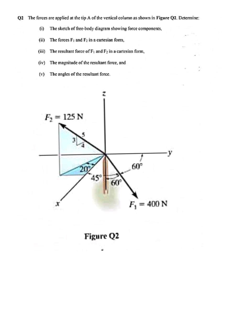
Transcribed Image Text:Q2 The forces are applied at the tip A of the vertical column as shown in Figure Q2. Determine:
(i) The sketch of free-body diagram showing force components,
(ii) The forces Fi and F2 in a cartesian form,
(iii) The resultant force of Fi and F2 in a cartesian form,
(iv) The magnitude of the resultant force, and
(v) The angles of the resultant force.
F = 125 N
45°
60
09
F, = 400 N
Figure Q2
Expert Solution
This question has been solved!
Explore an expertly crafted, step-by-step solution for a thorough understanding of key concepts.

Step by step
Solved in 2 steps with 2 images

Knowledge Booster


Learn more about
Need a deep-dive on the concept behind this application? Look no further. Learn more about this topic, mechanical-engineering and related others by exploring similar questions and additional content below.Recommended textbooks for you
International Edition---engineering Mechanics: St…
Mechanical Engineering
ISBN:
9781305501607
Author:
Andrew Pytel And Jaan Kiusalaas
Publisher:
CENGAGE L
International Edition---engineering Mechanics: St…
Mechanical Engineering
ISBN:
9781305501607
Author:
Andrew Pytel And Jaan Kiusalaas
Publisher:
CENGAGE L