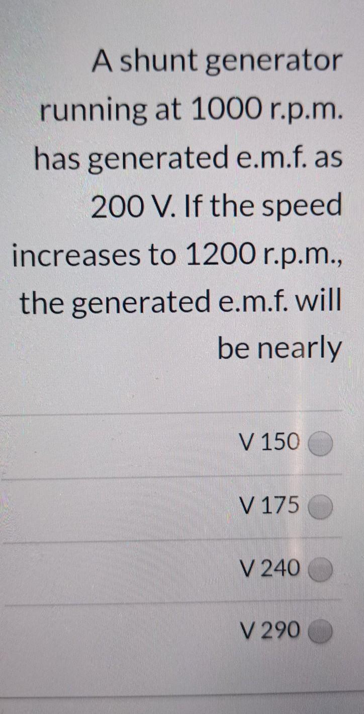
the generated e.m.f.


Q: y By means the current through the resstance R= luvr f superposition theorem, find 2 kuz 20v AMA…
A:
Q: VCE 1. a = 0.98 RE RC 2.5K2 prp tran sistor VDE = 0.7 V Determire: O Lo.Ic, SE O vec Vec VcE る う
A: We need to find out current and voltage for given circuit
Q: Determine current through each diode respectively in the circuit shown. Use simplified model. Assume…
A: The solution is given below
Q: b 75 82 50 nF a d 1 sin2pi100t 2 sin2pi100t 20 nF
A: The solution is given below
Q: R = 200 XL = 300 ú = 30V <60° Xc = 400
A: We need to find out current and voltage for the given circuit
Q: Ql: A) A 30, 3 wires T.L system work by 380 KV between lines to supply a load with lagging power…
A: Since you have asked multiple questions in a single request, we will be answering only the 1st…
Q: (a) Give three reasons why power protection is important. (b) Name three types of disturbances seen.
A:
Q: Q3) Find the quality for the circuit shown in Fig.2 by using approximate parallel resonant circuit.…
A:
Q: 1. For the circuit below, assume i(t) =t• u(t) mA with t in ms. For example, this assumption means…
A: The solution is given below
Q: atts. a. I*2R(read I squared R) b. Elcosθ c. both a and b d. conjugate method 3. The product…
A: Through these questions the basic understanding of apparent power, real power and reactive power is…
Q: In the figure the current in resistance 6 is ig = 1.38A and the resistances are R1 = R2 = R3 = 2.01…
A: In this question we will find battery emf E ...
Q: In parallel RL circuit, there are 5A RMS in the resistive branch and 7A RMS in the inductive branch.…
A:
Q: If we were to implement the following functions using only 2x4 decoders with enable inputs, and 2-…
A: We need to design desired Function .
Q: (difficult) A PD (proportional plus derivative) controller is required to compensate the Angle…
A: Given data Angle sufficiency=45 Pole location=(-2,j2)
Q: before it moves the following: 50 100 1H 1 F 20 2A(T 100 20v 50 HH
A: We need to find out time constant for the given circuit
Q: A digital system has a clock generator that produces pulses at a frequency of 125 MHz draw a circuit…
A:
Q: =-6 V. uivalent model.
A: Solution- IDSS = 12 mAVP = -6 VTransfer Curve,ID vs VGS IDSS = drain current at VGS = 0 VP = VGS at…
Q: If the peak output voltage of full wave center-tapped rectifier is 24.3 V, then peak inverse voltage…
A: given here peak output voltage of full wave center-tapped rectifier is 24.3 V here we have to…
Q: Determine the mathematical model equations for the electrical circuit shown in figure 2. The circuit…
A:
Q: Q.1 Figure Q1(a) shows the waveform of an AC voltage denoted as v(t). (a) Determine the exponential…
A:
Q: Problem 2 Consider a binary communications channel. Logical 0 is encoded with +1 Volt, and logical 1…
A: Given that logical zero was received and that +1 volt was delivered here, the probability necessary…
Q: You need to use a magnitude comparator for a circuit you are building. You would like to compare two…
A: The 4-bit binary arder can be designed to work as many of the logic circuits , because it uses…
Q: VDD +20 V Rp 1.0 k2 C2 Vout R1 18 kN 10 μF Vin o RL 10 kN 10 μF R2 6.8 kN
A: The solution is given below
Q: Which of the following is the differential equation for a given spring of translational mechanical…
A:
Q: + VCE L= 0.98 Pnp trancist 2-5 KA YBE =0.7Y 2V 18 Deter mine: a) IB, Ici JE b) VRE , VRC , vCE
A: PNP transistor: This is a transistor in which in the n-layer two p-layer material are doped and in…
Q: 12. A voice with 5 minutes duration is sampled, converted to binary form and then produced a data…
A:
Q: In data transmission, both periodic analogue signals and non-periodic digital signals are used. Why
A: In this question we will write why in data transmission , both periodic and non periodic signal is…
Q: Find the current I, in this circuit. 3/0° A -j22
A: In this question we need to find a current Io
Q: 3. Clampers 20 V Ideal Ideal -20 V (b)
A: We need to give the output waveform of the above given circuit for the given input.
Q: a 502 252 100S2 502 10V e 7552 252 h 'f
A:
Q: 32552 502 31052 7552 -12V d.
A: We need to find out current by norton Theorm
Q: A transformer with 120 primary turns and 10 secondary turns is connected to a 240V AC supply and…
A: We need to find current voltage and power for given circuit
Q: Find the synchronous impedance of a 3-phase synchronous generator in which a given field current…
A:
Q: An AC voltage peak value of 20 Volts is connected in series with a silicon diode and load resistance…
A: here 20 v source is connected to positive terminal of the battery to make the diode to operate in…
Q: (1) Simplify the Boolean expression: ((B + C) + ĀD)(Ā+B) (C + D) (2) Draw the logic diagram…
A: CMOS: It is a semiconductor device that is a combination of the PMOS and NMOS circuits.
Q: rtlov loka Vth: 2V
A:
Q: two capacitors are connected in series across a 120 V dc source has a total capacitance of 6 uF. One…
A: In this question we have to find out voltage across unknown capacitance in series connected…
Q: Given the closed loop system,
A:
Q: VEE RE Re 6= 180 pnp x %3D I1 2 knk. b.2 kn 43 kn kr minia) DB, Ic, TE , I, , Iz b) VRE, VRC N CE,
A:
Q: M) + IsV 21M I.z ka OMa Iks het ves Vos. Ig Toss= 12MA
A: FET: The field- effect transistor(FET) is a semiconductor device that controls the flow of…
Q: Calculate static resistance RD of a diode having D = 30 mA and VD = %3D %3D 0.75 V. 25 ohms 0.025…
A: Given, VD = 0.75 V ID = 30 mA
Q: 5. f lov lo=kn (Vos-Ven)" kn= 0.1 mA [v? RD Let R, tRz= (00 t Vas Design te circiit cuch mat I9-…
A:
Q: If a half-wave rectifier is used with 117-V rms ac, the average dc output voltage is about: O 117 V…
A: Out put DC voltage of half wave rectifier is given as Vo=(Vm/π) Where Vm= maximum voltage Vm= √2…
Q: Create a subroutine using registers AX and BX with POP instructions, that subtract two 16bit…
A:
Q: Q3: Compare and contrast Microprocessor with Microcontroller in detailed
A: The comparison between microcontroller and microprocessor are given as below
Q: A resistor and a capacitor are connected in series with a variable inductor. When the circuit is…
A:
Q: Q4. The signal x(t) given by x(t) = 1+ 2 sin(80nt) + 1.5 cos(300nt) + 0.5 cos(375nt) + 0.7sin…
A: Given the signal: x(t)=1+2sin(80πt)+1.5cos(300πt)+0.5cos(375πt)+0.7sin(815πt) is applied to the…
Q: The block having transfer functions G1 = 1/ (s+2); G2 = 1/ (s+5); G3 = (s+1) / (s+3); are in…
A: In this question we need to find a equivalent transfer function of the given system
Q: A voltage v = 120 sin 377t V is applied across a pure capacitance of 100μF, Determine the time…
A: This question belongs to circuit theory. It is based on the concept of relation among voltage and…
Q: Q18. What will be the operating power factor of a 3-phase induction motor, whose ra Hz, 120 hp, and…
A: In this question we will find operating power factor of induction motor... Note :- as per our…

Step by step
Solved in 2 steps with 2 images


- Suppose two generators supplying a load. Generator-1 has a no-load frequency of 61.5 Hz and a slopesp1 of 1 MW/Hz. Generator-2 has a no-load frequency of 62 Hz and a slope sp2 of 1MW/Hz. The twogenerators are supplying a real load totaling 2.5 MW at 0.8 PF lagging. Draw the resulting systempower-frequency or house-diagrams. Determine (a) at what frequency is the system operating, andhow much power is supplied by each of the generators? (b) if an additional 0.75-MW load wereattached to this power system. What would the new system frequency be, and how much powerwould the each generator supply now? (c) with the system in the configuration described in part (b),what will the system frequency and generators power be if the governor set points on generator-1 areincreased by 0.5 Hz?a short three phase transmission line connected to 33kv 50 hertz generating station at starting and is required to supply a load of 10 MW at pointed start lagging power factor at 30 KV addresses in that is the minimum transmission efficiency is to be determined96% estimate the per face value of resistance and inductance of a lineA 3 phase, wye-connected salient-pole generator has on per phase basis Xd = 2 ohms, Xq = 1.5 ohms and R∅ = 0. When delivering its maximum power output to an infinite bus bar, the terminal and excitation voltages/phase are 1,430 V and 1,495 V, respectively. Find the power angle in electrical degrees at the above conditions
- A generating station has a maximum demand of 25,000 kW. Calculate the cost per unit generatedfrom the following data: Capital cost = P 120M; Annual load factor = 45%; Annual cost of fuel and oil = P6.5M ; Taxes, wagesand salaries etc. = P6M and Interest and depreciation = 13%Two generating stations A and B have the capacities 500MW and 800MW respectively are interconnected by a short line. The percentage speed regulations from no load to full load of the two stations are 2 and 3 respectively. Find the power generation at each station and power transfer through the line if the load on bus of each station in 200MW.Discuss about generator modeling and drive the formula for the real and reactive power supply it .
- Explain the effect of load power factor on the transmission efficiency? Subject Power Transmission and DistributionEstimate the distance over which a load of 15000 KW at p.f-0.8 lagging can be delivered by a 3-phase T.L having conductor each of resistance 0.8 2 per km the voltage at the receiving end is to be 132 KV and the losses in the line is to be 5% of received powerCAN YOU EXPLAIN THE OPERATIONS IN SENTENCES? For the maximum average power transfer in the circuit shown in Figure 2, use the impedance ZLand ZLFind the value of the maximum average power transferred to ?
- While the instantaneous electric power delivered by a single-phase generator under balanced steady-state conditions is a function of time havi ng two components of a constant and a double-frequency sinusoid, the total instantaneous electric power delivered by a three-phase generator under balanced steady-state conditions is a constant. (a) True (b) FalseConsider two interconnected voltage sources connected by a line of impedance Z=jX, as shown in Figure 2.27. (a) Obtain expressions for P12 and Q12. (b) Determine the maximum power transfer and the condition for it toA single-phase, 120V(rms),60Hz source supplies power to a series R-L circuit consisting of R=10 and L=40mH. (a) Determine the power factor of the circuit and state whether it is lagging or leading. (b) Determine the real and reactive power absorbed by the load. (c) Calculate the peak magnetic energy Wint stored in the inductor by using the expression Wint=L(Irms)2 and check whether the reactive power Q=Wint is satisfied. (Note: The instantaneous magnetic energy storage fluctuates between zero and the peak energy. This energy must be sent twice each cycle to the load from the source by means of reactive power flows.)
