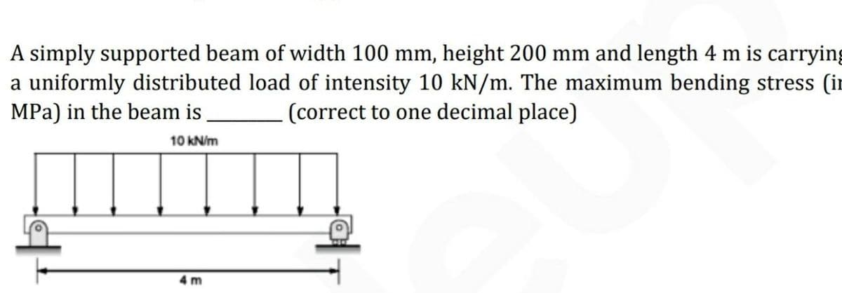
The maximum bending stress


Q: A bookshelf is made by placing a wooden plank on two brick supports. Where should the bricks be…
A: In the given problem, the weight of the books is not specify so consider the distributed weight of…
Q: If the shape in problem 5 is used for a beam with Mmax = 25 k-ft, what is the maximum bending…
A:
Q: I need working with an answer and an explanation of the concept on hand please. GIVEN: Beam as…
A:
Q: determine the displacement and slope at a point on a beam with example?
A: Draw the free-body diagram of the cantilever beam concentrated load P at the free end with a…
Q: What is the maximum magnitude of the bending moment caused by force F? If none, enter zero. Do not…
A: The bending moment at point B can be determined as,
Q: What is the internal normal force, shear force, and bending moment at point C, if F=40kN?
A: Given The value of force is F=40 kN. The load on beam consist of uniform distributed, uniform…
Q: Calculate the maximum bending stress
A:
Q: What is the maximum magnitude of the bending moment caused by force G? If none, enter zero. Do not…
A: It is required to determine the magnitude of the maximum bending moment by the force G.
Q: QUESTION 16 Calculate the Marin size factor k, for a non-rotating square beam loaded in fully…
A: Find the marin size factor.
Q: required width (bmin) if the allowable bending stress in the material is 16 MPa ? If the beam shown…
A:
Q: RN+10kips 25 kips RN+35 Find Maximum Bending Mement and Shear Force Values and locations. afs afs…
A: The free-body diagram of the beam is given below,
Q: Problem An I-section shown in Fig. 7.16, is simply supported over a span of 12 m. If the maximum…
A:
Q: What are Shear and Moment Diagrams?
A: Shear and moment diagrams are investigative tools that are utilized for structural analysis in order…
Q: If the beam has a solid rectangular cross-section, what does the shear formula become?
A:
Q: How is it possible to determine the bending stress developed within the curvature of the pole?
A: Yes, it is possible to determine the bending stress within the curvature of the pole using the…
Q: 1 A beam is subjected to a moment of 972 k-ft. If the material the beam is made out of has a yield…
A: Section modulus is used to determine the strength of materials which subject to loads, moment or…
Q: Draw the shear and moment diagram?
A:
Q: (a) Make Free Body Diagram (b) Find all the reactions labelled (c) Find the internal Shear and Mom…
A: as per guidelines we need to answer only first three subparts of question
Q: Draw the shear and moment diagrams for the loaded beam. After you have the diagrams, answer the…
A: The expression obtained by taking summation of forces along y-axis is, ∑Fy=0Fy-P-7 kN/m×10 m2=0…
Q: I in 6 in. 1 in. Determine the maximum shear stress in the beam. Express your answer to three…
A:
Q: State the assumptions made in deriving a bending formula.
A: If we don't make assumptions while deriving the bending equation, then the calculation will become…
Q: Explain Bending Moment with example?
A: A bending moment is the extend of bend in an element reaction induced in a structural element when…
Q: .How is the distribution of bending normal stress along the height of the beam section? Where does…
A: Given data What is the distribution of bending normal stress along the height of the beam section…
Q: 1. If the beam cross section is a rectangle with a breadth and depth of 6 in and 8 in respectively,…
A: Given that, RA+RD=100+80RA+RD=180 ......... 1Taking moment about A,100×2+80×6-RD×9=0RD=75.556…
Q: what are bending moment and shear force equations?
A:
Q: How can we obtain the maximum bending stress using the flexure formula?
A: Let us understand this by an example. Consider a beam applied with external bending moment M. This…
Q: Find the Shear and Bending Moment Diagrams.
A:
Q: Normally the cross section of a beam is first designed to resist theallowable bending stress.True or…
A: Cross-Section The cross-section is taken perpendicular to the longitudinal axis of the bar. All the…
Q: Ex: -1- Determine the minimum width (b) of the beam shown if bending (flexural) stress is not to…
A:
Q: Describe Bending Stress
A: Bending stress is the normal stress that an object encounters when it is subjected to a large load…
Q: Calculate the maximum shear.
A:
Q: Sketch the shear/moment diagrams for the following beams. Your diagrams should show the value of the…
A: Note:As per our guidelines we are supposed to answer only one question. Kindly repost other…
Q: Define the term bending stress?
A: The bending stress is the normal stress acting on a body when the body is subjected to a large load…
Q: A bookshelf is made by placing a wooden plank on two brick supports. Where should the bricks be…
A: Data given - Bookshelf made by placing a wooden plank on two brick support
Q: Define the term Bending Moment and when is it caused?
A: Bending moment is the reaction induced in the ember when an external force or moment acts on it. It…
Q: When does the maximum bending moment of a bar occur?
A: Bending moment When an outer force is applied on a beam, a reaction occurs in the beam, which causes…
Q: How can we determine the bending stress at the corner of the shaft?
A: From flexure formula we have σstress =M×yI ; .................................1where σstress…
Q: What will the shear force and bending moment diagram look like for the beam subjected to a point and…
A: Find Choose the correct SFD and BMD diagram for the given beam.
Q: Why does a bending design require a determination of the beam’s section modulus?
A: Section modulus is the direct measure of the strength of the steel. It is a geometric property for a…
Q: he lightest W-shape for the beam shown if the working stress in bending is 20 ksi. What is the…
A: ∑Mc=0By×16-2000×24-250×16×8+2000×8=0By=4000lb ∑Fy=0By+Cy-2000-2000-250×16=0Cy=4000lb…
Q: Why should the moment at the section be equivalent to the moment caused by the stress distribution?
A: The moment at the section should be equivalent to the moment caused by the stress distribution to…
Q: calculate the maximum bending stress when the shaft is rotating at 80% of the critical speed
A:
Q: What happens when the internal shear or moment in the beam is maximum?
A:
Q: How can we assume that the shear stress is constant over the cross-sectional area of the beam's web?
A: Given Shear stress Cross-sectional area of the beam’s web To find Procedure to assume constant
Q: We are using a section of square stock of aluminum in an upcoming design. We have calculated that…
A: Given: To determine the maximum transverse shear stress.
Q: Find Out Shear and moment equations
A:
Q: What are the three conditions to be met for the bending of straight members?
A: Given data⇒bending of straight membersProblem definition⇒Problem says what are the three conditions…


Trending now
This is a popular solution!

Step by step
Solved in 2 steps


- A rectangular beam with semicircular notches, as shown in part b of the figure, has dimensions h = 120 mm and h1= 100 mm. The maximum allowable bending stress in the plastic beam is emix = 6 M Pa, and the bending moment is M = 150 N · m. Determine the minimum permissible width bminof the beam..10 A built-up bourn supporting a condominium balcony is made up of a structural T (one half of a W 200 x 31.3) for the top flange and web and two angles (2 L 2 / b / 6.4. long legal back-lo-backl lot the bottom flange and web. as shown. The beam is subjected to a bending moment .1/ having its vector at an angle ft lo the z axis (see figure). Determine the or ion ta I ion of the neutral axis and calculate the maximum tensile stress ir, and maximum compressive stress tr. in ".he beam. .Assume that 9 = 30°andM = 15 kN · m. Use the numerical properties: c =4.111mm, c2 =4.169 mm, of = 134 mm, I, = 76 mm, A = 4144 mm 3 =3.88 X 106 mm 4, and = 34.18 X 10 mm 4.The cross section of a rectangular beam having a width b and height h is shown in part a of the figure. For reasons unknown to the beam designer, it is planned to add structural projections of width b/9 and height d/9 the top and bottom of the beam (see part b of the figure). For what values of d is the bending-moment capacity of the beam increased? For what values is it decreased?
- A rectangular beam with semicircular notches, as shown in part b of the figure, has dimensions h = 0,88 in. and h1 = 0.80 in. The maximum allowable bending stress in the metal beam is emax = 60 ksi, and the bending moment is M = 600 lb-in. Determine the minimum permissible width bminof the beam.A two-axle carriage that is part of an over head traveling crane in a testing laboratory moves slowly across a simple beam AB (sec figure). The load transmitted to the beam from the front axle is 2200 lb and from the rear axle is 3800 lb. The weight of the beam itself may be disregarded. Determine the minimum required section modulus S for the beam if the allowable bending stress is 17,0 ksi, the length of the beam is 18 ft, and the wheelbase of the carriage is 5 ft. Select the most economical I-beam (S shape) from Table F-2(a), Appendix F.A simple beam ACE is constructed with square cross sections and a double taper (see figure). The depth of the beam at the supports is dAand at the midpoint is dc= 2d 4. Each half of the beam has length L. Thus, the depth and moment of inertia / at distance x from the left-hand end are, respectively, in which IAis the moment of inertia at end A of the beam. (These equations are valid for .x between 0 and L, that is, for the left-hand half of the beam.) Obtain equations for the slope and deflection of the left-hand half of the beam due to the uniform load. From the equations in part (a), obtain formulas for the angle of rotation 94at support A and the deflection Scat the midpoint.
- A simple beam A B of a span length L = 24 ft is subjected to two wheel loads acting at a distance d = 5 ft apart (see figure). Each wheel transmits a load P = 3.0 kips, and the carriage may occupy any position on the beam. Determine the maximum bending stress Gmaxdue to the wheel loads if the beam is an I-beam having section modulus S = 16.2 in3. If d = 5 ft. Find the required span length L to reduce the maximum stress in part (a) to 18 ksi. If L = 24 ft, Find the required wheel spacing s to reduce the maximum stress in part (a) to 18 ksi.A rectangular beam with notches and a hole (see figure) has dimensions h = 5.5 in., h1= 5 in., and width b = 1.6 in. The beam is subjected to a bending moment M = 130 kip-in., and the maximum allowable bending stress in the material (steel) is emax = 42,000 psi. What is the smallest radius Rminthat should be used in the notches? What is the diameter dmixof the largest hole that should be drilled at the mid height of the beam?A beam of length L is designed to support a uniform load of intensity q (see figure). If the supports of the beam are placed at the ends, creating a simple beam, the maximum bending moment in the beam is qL2/8. However, if the supports of the beam are moved symmetrically toward the middle of the beam (as shown), the maximum bending moment is reduced. Determine the distance a between the supports so that the maximum bending moment in the beam has the smallest possible numerical value. Draw the shear-force and bending-moment diagrams for this condition. Repeat part (a) if the uniform load is replaced with a triangularly distributed load with peak intensity q0= q at mid-span (see Fig. b).
- A frame ABCD is constructed of steel wide-flange members (W8 x 21; E = 30 x ID6 psi) and subjected to triangularly distributed loads of maximum intensity q0acting along the vertical members (see figure). The distance between supports is L = 20 ft and the height of the frame is h = 4 ft. The members are rigidly connected at B and C. Calculate the intensity of load q0 required to produce a maximum bending moment of 80 kip-in. in the horizontal member BC. If the load q0 is reduced to one-half of the value calculated in part (a), what is the maximum bending moment in member BC? What is the ratio of this moment to the moment of 80 kip-in. in part (a)?The cross section of a sand wie h beam consisting of aluminum alloy faces and a foam core is shown in the figure. The width b of the beam is 8.0 in, the thickness I of the faces is 0.25 in., and the height hcof the core is 5.5 in. (total height h = 6.0 in). The moduli of elasticity are 10.5 × 10⁶ psi for the aluminum faces and 12.000 psi for the foam core. A bending moment M = 40 kip-in. acts about the z axis. Determine the maximum stresses in the faces and the core using (a) the general theory for composite beams and (b) the approximate theory for sandwich beams.A C 200 x 17.1 channel section has an angle with equal legs attached as shown; the angle serves as a lintel beam. The combined steel section is subjected to a bending moment M having its vector directed along the z axis, as shown in the figure. The cent roi d C of the combined section is located at distances xtand ycfrom the centroid (C1) of the channel alone. Principal axes yl and yvare also shown in the figure and properties Ix1,Iy1and 0pare given. Find the orientation of the neutral axis and calculate the maximum tensile stress exand maximum compressive stress if the angle is an L 76 x 76 x 6.4 section and M = 3.5 kN - m. Use the following properties for principal axes for the combined section:/^, = 18.49 X 10⁶ nrai4,/;| = 1.602 X 106 mm4, ep= 7.448*(CW),_r£ = 10.70 mm,andvf= 24.07 mm.