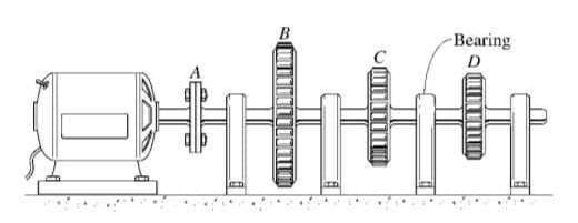
The motor on the left provides a torque of 5500 N•m to the gear shaft shown. The motor runs machines connected to gears B, C and D requiring torques of 3000 N•m, 1500 N•m and 1000 N•m respectively. A, B, C and D are spaced 2000 mm apart and the diameter of the shaft is 75 mm. The shear modulus of the shaft material is 80x109 N/m2. Determine: Minimum diameter required (in millimeters) if the shearing stress in the shaft is limited to 100x106 N/m2 Rotation of D with respect to A Note: Draw the Free Body Diagram, Compute for all of the necessary elements, Include the units/dimensions
The motor on the left provides a torque of 5500 N•m to the gear shaft shown. The motor runs machines connected to gears B, C and D requiring torques of 3000 N•m, 1500 N•m and 1000 N•m respectively. A, B, C and D are spaced 2000 mm apart and the diameter of the shaft is 75 mm. The shear modulus of the shaft material is 80x109 N/m2. Determine: Minimum diameter required (in millimeters) if the shearing stress in the shaft is limited to 100x106 N/m2 Rotation of D with respect to A Note: Draw the Free Body Diagram, Compute for all of the necessary elements, Include the units/dimensions

Automotive Technology: A Systems Approach (MindTap Course List)
6th Edition
ISBN:9781133612315
Author:Jack Erjavec, Rob Thompson
Publisher:Jack Erjavec, Rob Thompson
Chapter11: Lower End Theory And Service
Section: Chapter Questions
Problem 11RQ: What is the purpose of a thrust main bearing?

Related questions

Question
The motor on the left provides a torque of 5500 N•m to the gear shaft shown. The motor runs machines connected to gears B, C and D requiring torques of 3000 N•m, 1500 N•m and 1000 N•m respectively. A, B, C and D are spaced 2000 mm apart and the diameter of the shaft is 75 mm. The shear modulus of the shaft material is 80x109 N/m2.
Determine:
- Minimum diameter required (in millimeters) if the shearing stress in the shaft is limited to 100x106 N/m2
- Rotation of D with respect to A
Note: Draw the Free Body Diagram, Compute for all of the necessary elements, Include the units/dimensions, use the proper formula and round-off all the answers and final answers to 3 decimal places.
Transcribed Image Text:-Bearing
![Mechanics of Deformable Bodies
SHEAR
AND
МОМENT
EQUATIONS AND
DIAGRAMS
TORSION (Torsional Shearing Stress, t)
SHEAR AND MOMENT EQUATIONS (Procedure)
1. Compute the support reactions of the beam.
2. Divide the beam into segments so that the
loading within each segment is continuous.
3. ON EACH BEAM SEGMENT, introduce an
imaginary cutting plane within the segment,
located at a distance “x" from the left end of the
beam, that cuts the beam into parts.
Draw an FBD for the part of the beam lying to
the left. At the cut section, show V (Shear) and
M (Bending moment) acting in their positive
directions.
5. Determine the equations for V and M from the
equilibrium equations obtainable from the
FBDS. These expressions, which are usually
functions of x, are the shear force and bending
moment equation for the segment.
6. Do the preceding steps for all segments until you
obtain the shear and moment equation for all
segments.
4.
TP
Tr
Tmax=
T - torsional shearing stress
Tmax - maximum shear stress (N/m²)
T- twisting moment/ torque (Nm, lb-in, lb-ft)
p - distance from the center of the shaft
J- polar moment of inertia of the section (mm², in*)
r - radius of the shaft (m, mm, in,ft)
SHEAR AND MOMENT DIAGRAM
For solid cylindrical shaft:
Circular section
If the shear-force diagram is positive and looks like this ...
J =
D4
32
Vp
Ď J= = = 0.098
Linear
Linear
16T
32
Constant
(first order)
(first order)
Tmar =
(zero order)
For hollow cylindrical shaft:
Tube section
... then the bending-moment diagram looks like this:
J =
(Dª – dª)
32
J=
16TD
Quadratic
(second order)
Mp
Linear
Tmaz =
(first order)
7(Dª – dª)
Quadratie
(second order)
M.
M.
D- outside diameter
(mm)
d - inside diameter (mm)
Slope becomes
more positive
Slope becomes
less positive
Constant slope
(an upward ramp)
(a hill that
(an arch)
gets steeper)
ANGLE OF TWIST
Constant
(zero order)
TL
in radians
JG
Linear
(first order)
Linear
VE
(first order)
... then the bending-moment diagram looks like this:
M
ME
T- torque (Nmm)
L- length of shaft (mm)
G- shear modulus (MPa)
J- polar moment of inertia (mm4)
Quadratic
(second order)
Linear
(first order)
Quadratic
(second order)
M.
M
Slope becomes
more negative
Slope becomes
less negative
Constant slope
(a downward ramp)
(a waterfall)
(a valley)
E
G =
2(1+v)
Equation
Load Diagram
Shear-Force Diagram V
Bending-Moment Diagram M
Rule 1: Concentrated loads create discontinuities in the shcar-force diagram. [Equation (7.5)
Slepe -V
Positive jump
Slepe =
M.
E - modulus of elasticity
v - poisson's ratio
AV- P.
Rule 2: The change in shear force is equal to the area under the distributed-load curve. [Equation (7.3)]
POWER TRANSMITTED BY THE SHAFT
Av-v, -V, - dc
My
V. - V, - ada
A shaft rotating with a constant angular velocity o (in
radians per second) is being acted by a twisting moment
Т.
Rule 3: The slope of the V diagram is equal to the intensity of the distrihuted
Iw. [Equation (7.1))
Slepe -
P= To = 2nfT
Rule 4: The change in bending moment is equal to the area under the shear-force diagram. [Equation (7.4))
T- torque (N;m, ft:lb)
0 - angular velocity of the shaft (rad/s)
f- number of revolutions per second/ 1 cycle
P- power (watts, N'm)
r - radius
M, - M, = 5."V dt
Rule 5: The slope of the M diagram is oqual to the intensity of the shear force V. [Equation (7.2)]
Slepe - V,
Slope -
Siope V
f: 1 Hz (Hertz) = 1 cycle = 2nrad = W= 2nrf
Rule 6: Concentrated moments create discontinuities in the bending-moment disgram. [Equation (7.6)]
No elliet
shear force V
hending moent
AM --M.](/v2/_next/image?url=https%3A%2F%2Fcontent.bartleby.com%2Fqna-images%2Fquestion%2F446ab0cf-4f2d-4109-be70-3632d14fef78%2Fbf7bf77d-273f-4ada-924c-80ee60bb682b%2F3hh9m_processed.jpeg&w=3840&q=75)
Transcribed Image Text:Mechanics of Deformable Bodies
SHEAR
AND
МОМENT
EQUATIONS AND
DIAGRAMS
TORSION (Torsional Shearing Stress, t)
SHEAR AND MOMENT EQUATIONS (Procedure)
1. Compute the support reactions of the beam.
2. Divide the beam into segments so that the
loading within each segment is continuous.
3. ON EACH BEAM SEGMENT, introduce an
imaginary cutting plane within the segment,
located at a distance “x" from the left end of the
beam, that cuts the beam into parts.
Draw an FBD for the part of the beam lying to
the left. At the cut section, show V (Shear) and
M (Bending moment) acting in their positive
directions.
5. Determine the equations for V and M from the
equilibrium equations obtainable from the
FBDS. These expressions, which are usually
functions of x, are the shear force and bending
moment equation for the segment.
6. Do the preceding steps for all segments until you
obtain the shear and moment equation for all
segments.
4.
TP
Tr
Tmax=
T - torsional shearing stress
Tmax - maximum shear stress (N/m²)
T- twisting moment/ torque (Nm, lb-in, lb-ft)
p - distance from the center of the shaft
J- polar moment of inertia of the section (mm², in*)
r - radius of the shaft (m, mm, in,ft)
SHEAR AND MOMENT DIAGRAM
For solid cylindrical shaft:
Circular section
If the shear-force diagram is positive and looks like this ...
J =
D4
32
Vp
Ď J= = = 0.098
Linear
Linear
16T
32
Constant
(first order)
(first order)
Tmar =
(zero order)
For hollow cylindrical shaft:
Tube section
... then the bending-moment diagram looks like this:
J =
(Dª – dª)
32
J=
16TD
Quadratic
(second order)
Mp
Linear
Tmaz =
(first order)
7(Dª – dª)
Quadratie
(second order)
M.
M.
D- outside diameter
(mm)
d - inside diameter (mm)
Slope becomes
more positive
Slope becomes
less positive
Constant slope
(an upward ramp)
(a hill that
(an arch)
gets steeper)
ANGLE OF TWIST
Constant
(zero order)
TL
in radians
JG
Linear
(first order)
Linear
VE
(first order)
... then the bending-moment diagram looks like this:
M
ME
T- torque (Nmm)
L- length of shaft (mm)
G- shear modulus (MPa)
J- polar moment of inertia (mm4)
Quadratic
(second order)
Linear
(first order)
Quadratic
(second order)
M.
M
Slope becomes
more negative
Slope becomes
less negative
Constant slope
(a downward ramp)
(a waterfall)
(a valley)
E
G =
2(1+v)
Equation
Load Diagram
Shear-Force Diagram V
Bending-Moment Diagram M
Rule 1: Concentrated loads create discontinuities in the shcar-force diagram. [Equation (7.5)
Slepe -V
Positive jump
Slepe =
M.
E - modulus of elasticity
v - poisson's ratio
AV- P.
Rule 2: The change in shear force is equal to the area under the distributed-load curve. [Equation (7.3)]
POWER TRANSMITTED BY THE SHAFT
Av-v, -V, - dc
My
V. - V, - ada
A shaft rotating with a constant angular velocity o (in
radians per second) is being acted by a twisting moment
Т.
Rule 3: The slope of the V diagram is equal to the intensity of the distrihuted
Iw. [Equation (7.1))
Slepe -
P= To = 2nfT
Rule 4: The change in bending moment is equal to the area under the shear-force diagram. [Equation (7.4))
T- torque (N;m, ft:lb)
0 - angular velocity of the shaft (rad/s)
f- number of revolutions per second/ 1 cycle
P- power (watts, N'm)
r - radius
M, - M, = 5."V dt
Rule 5: The slope of the M diagram is oqual to the intensity of the shear force V. [Equation (7.2)]
Slepe - V,
Slope -
Siope V
f: 1 Hz (Hertz) = 1 cycle = 2nrad = W= 2nrf
Rule 6: Concentrated moments create discontinuities in the bending-moment disgram. [Equation (7.6)]
No elliet
shear force V
hending moent
AM --M.
Expert Solution
This question has been solved!
Explore an expertly crafted, step-by-step solution for a thorough understanding of key concepts.

Step by step
Solved in 2 steps with 2 images

Knowledge Booster


Learn more about
Need a deep-dive on the concept behind this application? Look no further. Learn more about this topic, mechanical-engineering and related others by exploring similar questions and additional content below.Recommended textbooks for you
Automotive Technology: A Systems Approach (MindTa…
Mechanical Engineering
ISBN:
9781133612315
Author:
Jack Erjavec, Rob Thompson
Publisher:
Cengage Learning
Automotive Technology: A Systems Approach (MindTa…
Mechanical Engineering
ISBN:
9781133612315
Author:
Jack Erjavec, Rob Thompson
Publisher:
Cengage Learning