The network N1 shown in Figure 123(a) contains linear RLC components. The driving- point input impedance Zin(j@) at the cyclic frequency f of 40KHZ is to be determined at te minals A-B. With the component values shown on the schematic, apply phasor compo- nents to calculate Zin(j@) and replace Ni with this complex impedance at A-B as shown in Figure 123(b). A A R1 1502 2202 R4 L5 1.0mH Ein(jw) C2 7.2nF Zin(jw) 33nF R7 L3 2.2mH C6 4702 N1 (a) (b) 0000
The network N1 shown in Figure 123(a) contains linear RLC components. The driving- point input impedance Zin(j@) at the cyclic frequency f of 40KHZ is to be determined at te minals A-B. With the component values shown on the schematic, apply phasor compo- nents to calculate Zin(j@) and replace Ni with this complex impedance at A-B as shown in Figure 123(b). A A R1 1502 2202 R4 L5 1.0mH Ein(jw) C2 7.2nF Zin(jw) 33nF R7 L3 2.2mH C6 4702 N1 (a) (b) 0000

Introductory Circuit Analysis (13th Edition)
13th Edition
ISBN:9780133923605
Author:Robert L. Boylestad
Publisher:Robert L. Boylestad
Chapter1: Introduction
Section: Chapter Questions
Problem 1P: Visit your local library (at school or home) and describe the extent to which it provides literature...

Related questions

Question
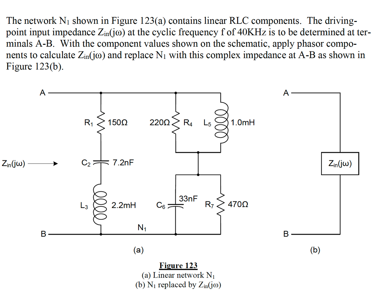
Transcribed Image Text:The network N1 shown in Figure 123(a) contains linear RLC components. The driving-
point input impedance Zin(jo) at the cyclic frequency f of 40KHZ is to be determined at ter-
minals A-B. With the component values shown on the schematic, apply phasor compo-
nents to calculate Zin(jo) and replace N1 with this complex impedance at A-B as shown in
Figure 123(b).
A
A
R1
1502
2200
R4
L5
1.0mH
Zin(jw)
C2
7.2nF
Zin(jw)
33nF
R7
L3
2.2mH
C6
4702
N1
В
В
(a)
(b)
Figure 123
(a) Linear network N1
(b) Ni replaced by Zin(jm)
0000
ell
Expert Solution
This question has been solved!
Explore an expertly crafted, step-by-step solution for a thorough understanding of key concepts.

This is a popular solution!

Trending now
This is a popular solution!

Step by step
Solved in 3 steps with 3 images

Knowledge Booster


Learn more about
Need a deep-dive on the concept behind this application? Look no further. Learn more about this topic, electrical-engineering and related others by exploring similar questions and additional content below.Recommended textbooks for you
Introductory Circuit Analysis (13th Edition)
Electrical Engineering
ISBN:
9780133923605
Author:
Robert L. Boylestad
Publisher:
PEARSON

Delmar's Standard Textbook Of Electricity
Electrical Engineering
ISBN:
9781337900348
Author:
Stephen L. Herman
Publisher:
Cengage Learning

Programmable Logic Controllers
Electrical Engineering
ISBN:
9780073373843
Author:
Frank D. Petruzella
Publisher:
McGraw-Hill Education
Introductory Circuit Analysis (13th Edition)
Electrical Engineering
ISBN:
9780133923605
Author:
Robert L. Boylestad
Publisher:
PEARSON
Delmar's Standard Textbook Of Electricity
Electrical Engineering
ISBN:
9781337900348
Author:
Stephen L. Herman
Publisher:
Cengage Learning
Programmable Logic Controllers
Electrical Engineering
ISBN:
9780073373843
Author:
Frank D. Petruzella
Publisher:
McGraw-Hill Education

Fundamentals of Electric Circuits
Electrical Engineering
ISBN:
9780078028229
Author:
Charles K Alexander, Matthew Sadiku
Publisher:
McGraw-Hill Education

Electric Circuits. (11th Edition)
Electrical Engineering
ISBN:
9780134746968
Author:
James W. Nilsson, Susan Riedel
Publisher:
PEARSON

Engineering Electromagnetics
Electrical Engineering
ISBN:
9780078028151
Author:
Hayt, William H. (william Hart), Jr, BUCK, John A.
Publisher:
Mcgraw-hill Education,