The simplified Boolean equations for the Stopwatch Finite State Machine Controller: NSO = NS₁ = Zero = Running = Stopped =
The simplified Boolean equations for the Stopwatch Finite State Machine Controller: NSO = NS₁ = Zero = Running = Stopped =
C++ Programming: From Problem Analysis to Program Design
8th Edition
ISBN:9781337102087
Author:D. S. Malik
Publisher:D. S. Malik
Chapter5: Control Structures Ii (repetition)
Section: Chapter Questions
Problem 20PE: When you borrow money to buy a house, a car, or for some other purpose, you repay the loan by making...

Related questions
Question
Computer science
Please help with part D only. Please.
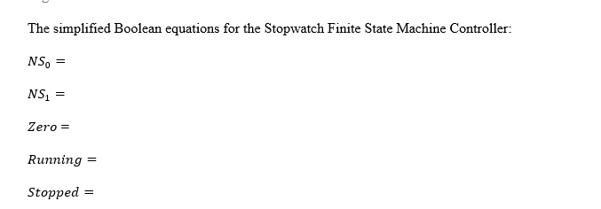
Transcribed Image Text:The simplified Boolean equations for the Stopwatch Finite State Machine Controller:
NS =
NS₁ =
Zero =
Running =
Stopped =
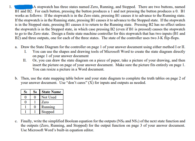
Transcribed Image Text:1.
A stopwatch has three states named Zero, Running, and Stopped. There are two buttons, named
B1 and B2. For each button, pressing the button produces a 1 and not pressing the button produces a 0. B1
works as follows: If the stopwatch is in the Zero state, pressing B1 causes it to advance to the Running state.
If the stopwatch is in the Running state, pressing B1 causes it to advance to the Stopped state. If the stopwatch
is in the Stopped state, pressing B1 causes it to return to the Running state. Pressing B2 has no effect unless
the stopwatch is in the Stopped state, in which case pressing B2 (even if B1 is pressed) causes the stopwatch
to go to the Zero state. Design a finite state machine controller for this stopwatch that has two inputs (B1 and
B2) and three outputs, one for each of the three states. The state of the controller uses two J-K flip-flops.
a. Draw the State Diagram for the controller on page 1 of your answer document using either method I or II.
I. You can use the shapes and drawing tools of Microsoft Word to create the state diagram directly
on page 1 of your answer document
Or, you can draw the state diagram on a piece of paper, take a picture of your drawing, and then
insert the picture on page of your answer document. Make sure the picture fits entirely on page 1.
You can resize a picture in a Word document.
II.
b. Then, use the state mapping table below and your state diagram to complete the truth tables on page 2 of
your answer document. Use "don't cares" (X) for inputs and outputs as needed.
Si So
0
0
1
0
Running
1 Stopped
State Name
Not Used
Zero
0
1
1
c. Finally, write the simplified Boolean equation for the outputs (NSo and NS1) of the next state function and
the outputs (Zero, Running, and Stopped) for the output function on page 3 of your answer document.
Use Microsoft Word's built-in equation editor.
Expert Solution
This question has been solved!
Explore an expertly crafted, step-by-step solution for a thorough understanding of key concepts.

Step by step
Solved in 3 steps

Knowledge Booster


Learn more about
Need a deep-dive on the concept behind this application? Look no further. Learn more about this topic, computer-science and related others by exploring similar questions and additional content below.Recommended textbooks for you
C++ Programming: From Problem Analysis to Program…
Computer Science
ISBN:
9781337102087
Author:
D. S. Malik
Publisher:
Cengage Learning
C++ Programming: From Problem Analysis to Program…
Computer Science
ISBN:
9781337102087
Author:
D. S. Malik
Publisher:
Cengage Learning