The solid shaft is fixed to the support at C and subjected to the torsional loadings and axial load P as shown. a. Determine the torsional shear stress at Point A (50mm from the center) and Point B (on the Surface) b. Determine the absolute maximum torsional shear stress in the shaft. c. sketch the state of stress at point A and draw its corresponding Mohr’s Circle of stress. compute the principal stresses and maximum in-plane stress. T=10.38kN-m
The solid shaft is fixed to the support at C and subjected to the torsional loadings and axial load P as shown. a. Determine the torsional shear stress at Point A (50mm from the center) and Point B (on the Surface) b. Determine the absolute maximum torsional shear stress in the shaft. c. sketch the state of stress at point A and draw its corresponding Mohr’s Circle of stress. compute the principal stresses and maximum in-plane stress. T=10.38kN-m

Principles of Geotechnical Engineering (MindTap Course List)
9th Edition
ISBN:9781305970939
Author:Braja M. Das, Khaled Sobhan
Publisher:Braja M. Das, Khaled Sobhan
Chapter15: Slope Stability
Section: Chapter Questions
Problem 15.28P

Related questions

Question
The solid shaft is fixed to the support at C and subjected to the torsional loadings and axial load P as shown.
a. Determine the torsional shear stress at Point A (50mm from the center) and Point B (on the Surface)
b. Determine the absolute maximum torsional shear stress in the shaft.
c. sketch the state of stress at point A and draw its corresponding Mohr’s Circle of stress. compute the principal stresses and maximum in-plane stress.
T=10.38kN-m
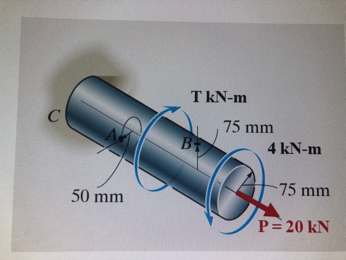
Transcribed Image Text:C
50 mm
T kN-m
B₁
75 mm
4 kN-m
Q
75 mm
P= 20 kN
Expert Solution
This question has been solved!
Explore an expertly crafted, step-by-step solution for a thorough understanding of key concepts.

This is a popular solution!

Trending now
This is a popular solution!

Step by step
Solved in 4 steps with 4 images

Knowledge Booster


Learn more about
Need a deep-dive on the concept behind this application? Look no further. Learn more about this topic, civil-engineering and related others by exploring similar questions and additional content below.Recommended textbooks for you
Principles of Geotechnical Engineering (MindTap C…
Civil Engineering
ISBN:
9781305970939
Author:
Braja M. Das, Khaled Sobhan
Publisher:
Cengage Learning
Principles of Geotechnical Engineering (MindTap C…
Civil Engineering
ISBN:
9781305970939
Author:
Braja M. Das, Khaled Sobhan
Publisher:
Cengage Learning