The voltage pulse shown in is applied to the ideal integrating amplifier shown in and v. (0) = 0. Vg (mv) 200 0 -200 250 25 kn 500 5 MO w 400 nF HE 6 V -6V 1 (ms)
The voltage pulse shown in is applied to the ideal integrating amplifier shown in and v. (0) = 0. Vg (mv) 200 0 -200 250 25 kn 500 5 MO w 400 nF HE 6 V -6V 1 (ms)

Delmar's Standard Textbook Of Electricity
7th Edition
ISBN:9781337900348
Author:Stephen L. Herman
Publisher:Stephen L. Herman
Chapter18: Resistive-inductive Parallel Circuits
Section: Chapter Questions
Problem 13PP: In an R-L parallel circuit, IT=1.25 amps, R=1.2k, and XL=1k. Find IR

Related questions

Question
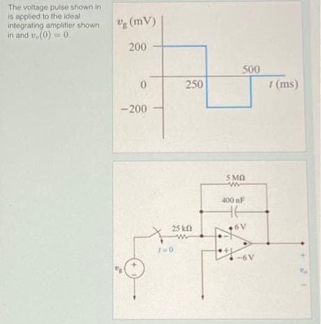
Transcribed Image Text:The voltage pulse shown in
is applied to the ideal
integrating amplifier shown
in and v. (0) = 0.
Vg (mv)
200
0
-200
4
250
25 kn
ww
1=0
500
5 MO
w
400 nF
HE
6V
-6V
1 (ms)
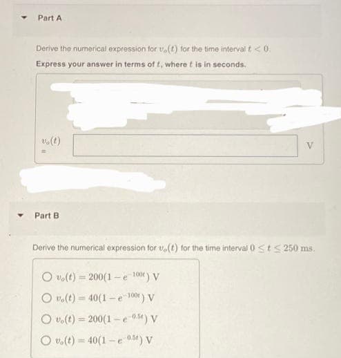
Transcribed Image Text:Part A
Derive the numerical expression for u.(t) for the time interval t < 0.
Express your answer in terms of t, where t is in seconds.
vo(t)
=
Part B
V
Derive the numerical expression for u(t) for the time interval 0 ≤t≤ 250 ms.
Ovo(t)=200(1-e 100) V
Ovo(t)=40(1e-100) V
Ovo(t) 200(1-e-05) V
Ovo(t)=40(1-e 0.5t) V
Expert Solution
This question has been solved!
Explore an expertly crafted, step-by-step solution for a thorough understanding of key concepts.

This is a popular solution!

Trending now
This is a popular solution!

Step by step
Solved in 3 steps with 7 images

Knowledge Booster


Learn more about
Need a deep-dive on the concept behind this application? Look no further. Learn more about this topic, electrical-engineering and related others by exploring similar questions and additional content below.Recommended textbooks for you
Delmar's Standard Textbook Of Electricity
Electrical Engineering
ISBN:
9781337900348
Author:
Stephen L. Herman
Publisher:
Cengage Learning
Delmar's Standard Textbook Of Electricity
Electrical Engineering
ISBN:
9781337900348
Author:
Stephen L. Herman
Publisher:
Cengage Learning