The yoke and rod connection assembly shown in the figure below is subjected to a tensile force of 5 kN. I Determine the tensile stress in each rod. Determine the shear stress in pin A between the members. If each rod is 600 mm long, determine the overall extension of the assembly. Ignore any stretch in the joint. 40 mm 5 kN. 30 mm A 25 mm 5 kN
The yoke and rod connection assembly shown in the figure below is subjected to a tensile force of 5 kN. I Determine the tensile stress in each rod. Determine the shear stress in pin A between the members. If each rod is 600 mm long, determine the overall extension of the assembly. Ignore any stretch in the joint. 40 mm 5 kN. 30 mm A 25 mm 5 kN

Mechanics of Materials (MindTap Course List)
9th Edition
ISBN:9781337093347
Author:Barry J. Goodno, James M. Gere
Publisher:Barry J. Goodno, James M. Gere
Chapter1: Tension, Compression, And Shear
Section: Chapter Questions
Problem 1.10.6P: Cable DB supports canopy beam OABC as shown in the figure. Find the required cross-sectional area of...

Related questions

Question
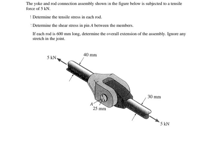
Transcribed Image Text:The yoke and rod connection assembly shown in the figure below is subjected to a tensile
force of 5 kN.
I Determine the tensile stress in each rod.
Determine the shear stress in pin A between the members.
If each rod is 600 mm long, determine the overall extension of the assembly. Ignore any
stretch in the joint.
40 mm
5 kN.
30 mm
25 mm
5 kN
Expert Solution
This question has been solved!
Explore an expertly crafted, step-by-step solution for a thorough understanding of key concepts.

This is a popular solution!

Trending now
This is a popular solution!

Step by step
Solved in 3 steps with 3 images

Knowledge Booster


Learn more about
Need a deep-dive on the concept behind this application? Look no further. Learn more about this topic, mechanical-engineering and related others by exploring similar questions and additional content below.Recommended textbooks for you
Mechanics of Materials (MindTap Course List)
Mechanical Engineering
ISBN:
9781337093347
Author:
Barry J. Goodno, James M. Gere
Publisher:
Cengage Learning
Mechanics of Materials (MindTap Course List)
Mechanical Engineering
ISBN:
9781337093347
Author:
Barry J. Goodno, James M. Gere
Publisher:
Cengage Learning