TLO 4: Compute subtransient currents and voltages during unsymmetrical faults in a power system. Solve the following problems: All solutions must be handwritten and will be converted to a single file-pdf format. Use 5 decimal places. The one-line diagram of a simple power system is shown in the figure. The neutral of each generator is grounded through a current-limiting reactor of 0.25/3 per unit on a 100- MVA base. The system data expressed in per unit on a common 100-MVA base is tabulated below. The generators are running on no-load at their rated voltage and rated frequency with their emfs in phase. Determine the fault current and voltages for the following faults. a. A single line-to-ground fault at bus 2 through a fault impedance Z, = j0.125 per unit. b. A line to line fault at bus 2 through a fault impedance Z, = j0.125 per unit. c. A double line to ground fault at bus 2 through a fault impedance Z, = j0.125 per unit.
TLO 4: Compute subtransient currents and voltages during unsymmetrical faults in a power system. Solve the following problems: All solutions must be handwritten and will be converted to a single file-pdf format. Use 5 decimal places. The one-line diagram of a simple power system is shown in the figure. The neutral of each generator is grounded through a current-limiting reactor of 0.25/3 per unit on a 100- MVA base. The system data expressed in per unit on a common 100-MVA base is tabulated below. The generators are running on no-load at their rated voltage and rated frequency with their emfs in phase. Determine the fault current and voltages for the following faults. a. A single line-to-ground fault at bus 2 through a fault impedance Z, = j0.125 per unit. b. A line to line fault at bus 2 through a fault impedance Z, = j0.125 per unit. c. A double line to ground fault at bus 2 through a fault impedance Z, = j0.125 per unit.

Power System Analysis and Design (MindTap Course List)
6th Edition
ISBN:9781305632134
Author:J. Duncan Glover, Thomas Overbye, Mulukutla S. Sarma
Publisher:J. Duncan Glover, Thomas Overbye, Mulukutla S. Sarma
Chapter7: Symmetrical Faults
Section: Chapter Questions
Problem 7.34P

Related questions

Concept explainers
Three-Phase Transformers
Three-segment transformers are a type of transformer used to transform voltages of electrical systems into three ranges. Two type transformers are shell-type transformer and core type transformer. In brief, it could be described because of the exquisite kinds of configurations.
Transformer
Ever since electricity has been created, people have started using it in its entirety. We see many types of Transformers in the neighborhoods. Some are smaller in size and some are very large. They are used according to their requirements. Many of us have seen the electrical transformer but they do not know what work they are engaged in.
Question
Transcribed Image Text:TLO 4: Compute subtransient currents and voltages during unsymmetrical faults
in a power system.
Solve the following problems: All solutions must be handwritten and will be
converted to a single file-pdf format. Use 5 decimal places.
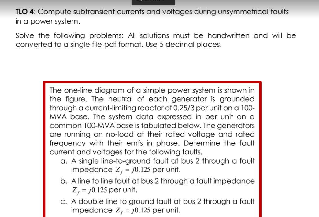
The one-line diagram of a simple power system is shown in
the figure. The neutral of each generator is grounded
through a current-limiting reactor of 0.25/3 per unit on a 100-
MVA base. The system data expressed in per unit on a
common 100-MVA base is tabulated below. The generators
are running on no-load at their rated voltage and rated
frequency with their emfs in phase. Determine the fault
current and voltages for the following faults.
a. A single line-to-ground fault at bus 2 through a fault
impedance Z, = j0.125 per unit.
b. A line to line fault at bus 2 through a fault impedance
Z, = j0.125 per unit.
c. A double line to ground fault at bus 2 through a fault
impedance Z, = j0.125 per unit.
%3D
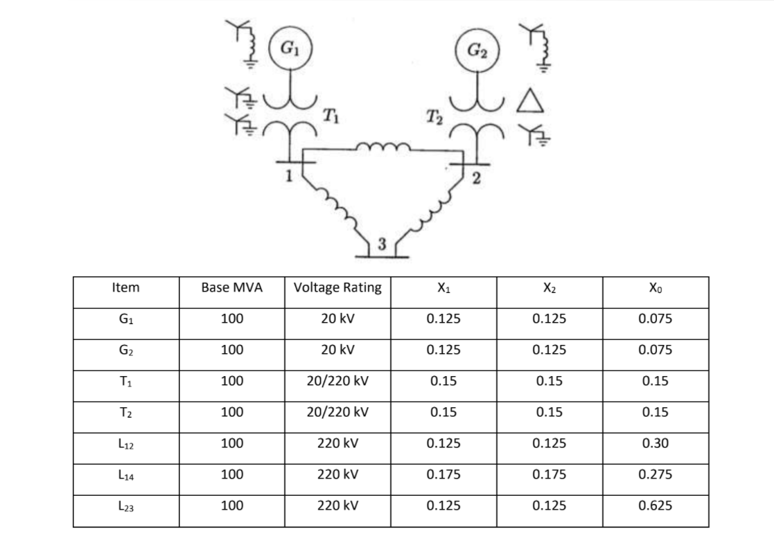
Transcribed Image Text:G1
T1
Item
Base MVA
Voltage Rating
X1
X2
Хо
G1
100
20 kV
0.125
0.125
0.075
G2
100
20 kV
0.125
0.125
0.075
T1
100
20/220 kV
0.15
0.15
0.15
T2
100
20/220 kV
0.15
0.15
0.15
L12
100
220 kV
0.125
0.125
0.30
L14
100
220 kV
0.175
0.175
0.275
L23
100
220 kV
0.125
0.125
0.625
产
Expert Solution
This question has been solved!
Explore an expertly crafted, step-by-step solution for a thorough understanding of key concepts.

Step by step
Solved in 7 steps with 6 images

Knowledge Booster


Learn more about
Need a deep-dive on the concept behind this application? Look no further. Learn more about this topic, electrical-engineering and related others by exploring similar questions and additional content below.Recommended textbooks for you
Power System Analysis and Design (MindTap Course …
Electrical Engineering
ISBN:
9781305632134
Author:
J. Duncan Glover, Thomas Overbye, Mulukutla S. Sarma
Publisher:
Cengage Learning

EBK ELECTRICAL WIRING RESIDENTIAL
Electrical Engineering
ISBN:
9781337516549
Author:
Simmons
Publisher:
CENGAGE LEARNING - CONSIGNMENT
Power System Analysis and Design (MindTap Course …
Electrical Engineering
ISBN:
9781305632134
Author:
J. Duncan Glover, Thomas Overbye, Mulukutla S. Sarma
Publisher:
Cengage Learning
EBK ELECTRICAL WIRING RESIDENTIAL
Electrical Engineering
ISBN:
9781337516549
Author:
Simmons
Publisher:
CENGAGE LEARNING - CONSIGNMENT