
Videos
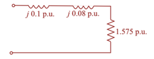
Consider a single-phase electric system shown in Figure 3.33. Transformers are rated as follows:
With the base in circuit Y chosen as

Trending nowThis is a popular solution!

Chapter 3 Solutions
Power System Analysis and Design (MindTap Course List)


- Consider the single-Line diagram of a power system shown in Figure 3.42 with equipment ratings given: Generator G1: 50MVA,13.2kV,x=0.15p.u. Generator G2: 20MVA,13.8kV,x=0.15p.u. Three-phase -Y transformer T1: 80MVA,13.2/165YkV,X=0.1p.u. Three-phase Y- transformer T2: 40MVA,165Y/13.8kV,X=0.1p.u. Load: 40MVA,0.8PFlagging,operatingat150kV Choose a base of 100 MVA for the system and 132-kV base in the transmission-line circuit. Let the load be modeled as a parallel combination of resistance and inductance. Neglect transformer phase shifts. Draw a per-phase equivalent circuit of the system showing all impedances in per unit.arrow_forwardConsider Figure 3.25 of the text for a transformer with off-nominal turns ratio. (i) The per-unit equivalent circuit shown in part (c) contains an ideal transformer which cannot be accommodated by some computer programs. (a) True (b) False (ii) In the - circuit representation for real c in part (d), the admittance parameters Y11 and Y12 would be unequal. (a) True (b) False (iii) For complex c, can the admittance parameters be synthesized with a passive RLC circuit? (a) Yes (b) Noarrow_forwardConsider the single-line diagram of the power system shown in Figure 3.38. Equipment ratings are Generator 1: 1000MVA,18kV,X=0.2perunit Generator 2: 1000MVA,18kV,X=0.2p.u. Synchronous motor 3: 1500MVA,20kV,X=0.2p.u. Three-phase -Y transformers T1,T2,T3,T4,: 1000MVA,500kV,Y/20kV,X=0.1p.u. Three-phase YY transformer T5: 1500MVA,500kV,Y/20kVY,X=0.1p.u. Neglecting resistance, transformer phase shift, and magnetizing reactance, draw the equivalent reactance diagram. Use a base of 100 MA and 500 kV for the 50-ohm line. Determine the per-unit reactances.arrow_forward
- PowerWorid Simulator case Problem 3_60 duplicates Example 3.13 except that a resistance term of 0.06 per unit has been added to the transformer and 0.05 per unit to the transmission line. Since the system is no longer lossless, a field showing the real power losses has also been added to the oneline. With the LTC tap fixed at 1.05, plot the real power losses as the phase shift angle is varied from 10 to +10 degrees. What value of phase shift minimizes the system losses?arrow_forwardConsider the three single-phase two-winding transformers shown in Figure 3.37. The high-voltage windings are connected in Y. (a) For the low-voltage side, connect the windings in , place the polarity marks, and label the terminals a, b, and c in accordance with the American standard. (b) Relabel the terminals a, b, and c such that VAN is 90 out of phase with Va for positive sequence.arrow_forwardConsider three ideal single-phase transformers (with a voltage gain of ) put together as three-phase bank as shown in Figure 3.35. Assuming positive-sequence voltages for Va,Vb, and Vc find Va,Vb, and VC. in terms of Va,Vb, and Vc, respectively. (a) Would such relationships hold for the line voltages as well? (b) Looking into the current relationships, express IaIb and Ic in terms of IaIb and Ic respectively. (C) Let S and S be the per-phase complex power output and input. respectively. Find S in terms of S.arrow_forward
- In developing per-unit equivalent circuits for three-phase transformers. under balanced three-phase operation. (i) A common Sbase is selected for both the H and X terminals. (ii) The ratio of the voltage bases Vbase/VbaseX is selected to be equal to the ratio of the rated line-to-line voltages VratedHLL/VratedXLL. (a) Only one of the above is true. (b) Neither is true. (C) Both statements are true.arrow_forwardConsider Figure 3.4. For an ideal phase-shifting transformer, the imda nce is unchanged when it is referred from one side to the other. (a) True (b) Falsearrow_forwardConsider the oneline diagram shown in Figure 3.40. The three-phase transformer bank is made up of three identical single-phase transformers, each specified by X1=0.24 (on the low-voltage side), negligible resistance and magnetizing current, and turns ratio =N2/N1=10. The transformer bank is delivering 100 MW at 0.8 p.f. lagging to a substation bus whose voltage is 230 kV. (a) Determine the primary current magnitude, primary voltage (line-to-line) magnitude, and the three-phase complex power supplied by the generator. Choose the line-to-neutral voltage at the bus, Va as the reference Account for the phase shift, and assume positive-sequence operation. (b) Find the phase shift between the primary and secondary voltages.arrow_forward
- In developing per-unit circuits of systems such as the one shown in Figure 3.10. when moving across a transformer, the voltage base is changed in proportion to the transformer voltage ratings. (a) True (b) Falsearrow_forwardFigure 3.39 shows a oneline diagram of a system in which the three-phase generator is rated 300 MVA, 20 kV with a subtransient reactance of 0.2 per unit and with its neutral grounded through a 0.4- reactor. The transmission line is 64km long with a cries reactance of 0.5-/km. The three-phase transformer T1 is rated 350MVA.230/20kV with a leakage reactance of 0.1 per unit. Transformer T2 is composed of three single-phase transformers, each rated 100 MVA, 127/13.2kV with a leakage reactance of 0.1 per unit. Two 13.2kV motors M1 and M2 with a subtransient reactance of 0.2 per unit for each motor represent the load. M1 has a rated input of 200 MVA with its neutral grounded through a 0.4- current-limiting reactor, M2 has a rated input of 100 MVA with its neutral not connected to ground. Neglect phase shifts associated with the transformers. Choose the generator rating as base in the generator circuit and draw the positive-sequence reactance diagram showing all reactances in per unit.arrow_forwardReconsider Problem 3.64 with the change that now Tb includes both a transformer of the same turns ratio as Ta and a regulating transformer with a 4 phase shift. On the base of Ta, the impedance of the two comp onents of Tb is jO.1 per unit. Determine the complex power in per unit transmitted to the load through each transformer. Comment on how the transformers share the real and reactive pors.arrow_forward
 Power System Analysis and Design (MindTap Course ...Electrical EngineeringISBN:9781305632134Author:J. Duncan Glover, Thomas Overbye, Mulukutla S. SarmaPublisher:Cengage Learning