- Transformer Design You are requested in this practical to design a transformer which will have the following characteristics: Two windings, one primary and one secondary with an E-shape core. Vin = 220 V RMS 16 < Vout < 20 V RMS open circuits 14.5 V < Vout < 16 V on a 100 N resistor. 2 VA < S <5 VA apparent power. Show all steps of your design with calculation. Indicate current in primary and secondary in both open circuit and with 100 2 resistor. Simulate your transformer and show both input and output voltage with the 100 N load. Talk about your transformer and wire sizes.
- Transformer Design You are requested in this practical to design a transformer which will have the following characteristics: Two windings, one primary and one secondary with an E-shape core. Vin = 220 V RMS 16 < Vout < 20 V RMS open circuits 14.5 V < Vout < 16 V on a 100 N resistor. 2 VA < S <5 VA apparent power. Show all steps of your design with calculation. Indicate current in primary and secondary in both open circuit and with 100 2 resistor. Simulate your transformer and show both input and output voltage with the 100 N load. Talk about your transformer and wire sizes.

Power System Analysis and Design (MindTap Course List)
6th Edition
ISBN:9781305632134
Author:J. Duncan Glover, Thomas Overbye, Mulukutla S. Sarma
Publisher:J. Duncan Glover, Thomas Overbye, Mulukutla S. Sarma
Chapter6: Power Flows
Section: Chapter Questions
Problem 6.61P

Related questions

Question
Transformer design. Please ignore the frequency response part. Help with transformer design as much as possible. Make it a word document
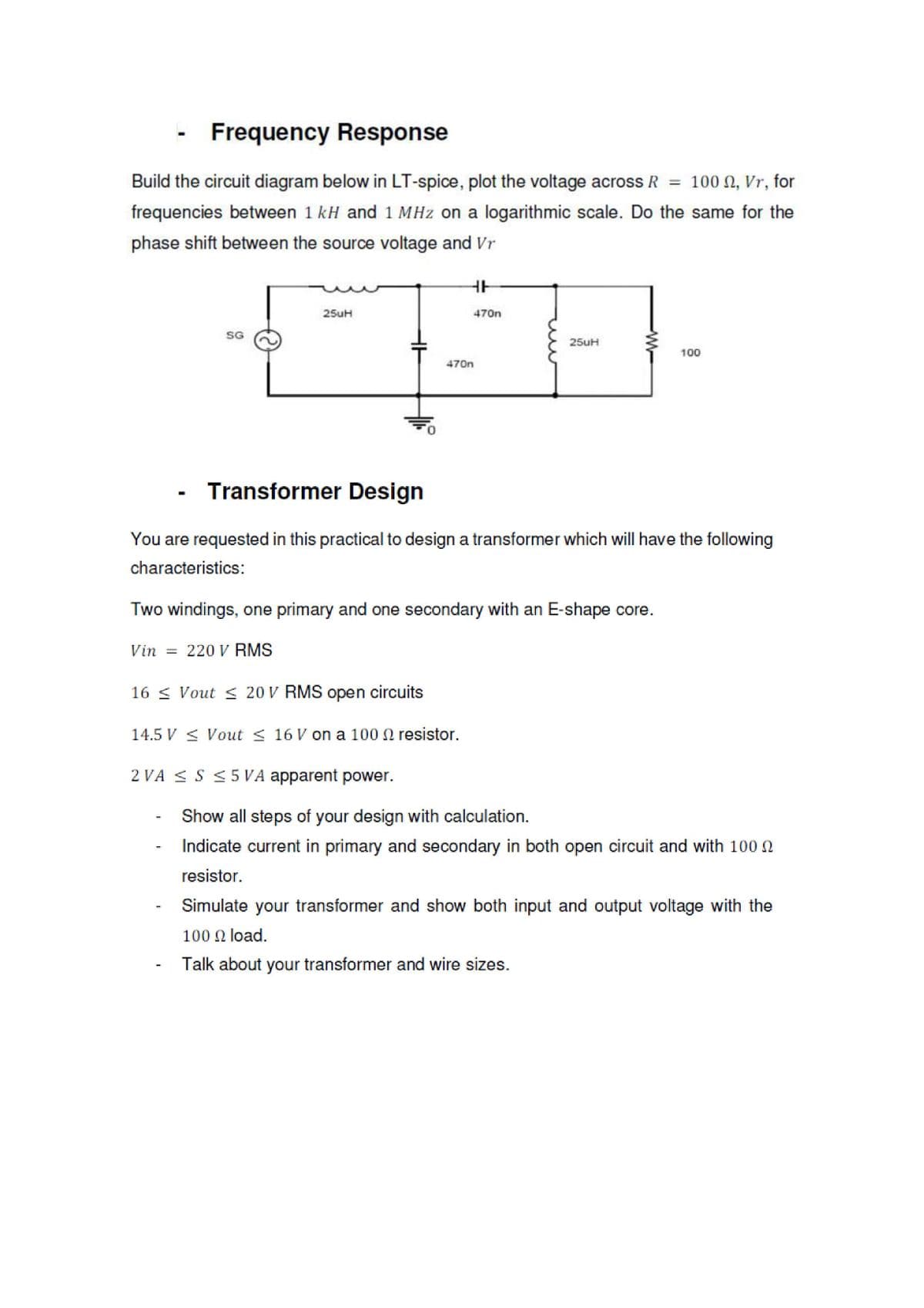
Transcribed Image Text:Frequency Response
Build the circuit diagram below in LT-spice, plot the voltage across R = 100 N, Vr, for
frequencies between 1 kH and 1 MHz on a logarithmic scale. Do the same for the
phase shift between the source voltage and Vr
25uH
470n
SG
25uH
100
470n
Transformer Design
You are requested in this practical to design a transformer which will have the following
characteristics:
Two windings, one primary and one secondary with an E-shape core.
Vin =
220 V RMS
16 < Vout < 20 V RMS open circuits
14.5 V < Vout < 16 V on a 100 N resistor.
2 VA < S < 5 VA apparent power.
Show all steps of your design with calculation.
Indicate current in primary and secondary in both open circuit and with 100 0
resistor.
Simulate your transformer and show both input and output voltage with the
100 N load.
Talk about your transformer and wire sizes.
Expert Solution
This question has been solved!
Explore an expertly crafted, step-by-step solution for a thorough understanding of key concepts.

Step by step
Solved in 4 steps with 8 images

Knowledge Booster


Learn more about
Need a deep-dive on the concept behind this application? Look no further. Learn more about this topic, electrical-engineering and related others by exploring similar questions and additional content below.Recommended textbooks for you
Power System Analysis and Design (MindTap Course …
Electrical Engineering
ISBN:
9781305632134
Author:
J. Duncan Glover, Thomas Overbye, Mulukutla S. Sarma
Publisher:
Cengage Learning
Power System Analysis and Design (MindTap Course …
Electrical Engineering
ISBN:
9781305632134
Author:
J. Duncan Glover, Thomas Overbye, Mulukutla S. Sarma
Publisher:
Cengage Learning