Transient analysis: 1) Use Thevenin's theorem to convert the circuit of Figure 1 to the circuit of Figure 2 by finding out the values of V1 and R1. Now using the circuit of Figure 2, find out the expression of i_c(t) as a function of time. Figure 1: 1 k? 1.25 k t = 0 8 V 3 kl 2 mA 1 µF- i.(t) Figure 2: R1 =? kN Vị =? V 1 µF vi(t) wps.com 2) Now we want to check if the superposition principle works in this case or not. First we turn the voltage source off and keep the current source on in the following Figure 1. Then we convert it to the circuit of Figure 2 using Thevenin's theorem. Now using the circuit of Figure 2, find out the expression of ic_1(t) as a function of time. Figure 1: 1 kN 1.25 kN t = 0 ov 3 kn 2 mA ( 1 µF Figure 2: R =? kN t= 0 V =? V 1 µF vic_1(t) 3) Now we turn the current source off and keep the voltage source on in the following Figure 1. Then we convert it to the circuit of Figure 2 using Thevenin's theorem. Now using the circuit of Figure 2, find out the expression of ic_2(t) as a function of time. Figure 1: 1 kN 1.25 k 8 V 3 kN, O mA 1 µF Figure R1 =? kf? t= 0 Vị =? V 1 µF v ic_2(t) 4) Is ic¡(1) + ic,(t) = ic(t) ? ( ic(t) being the expression that we found in step 1) Does the superposition principle work in this case for time varying current also?
Transient analysis: 1) Use Thevenin's theorem to convert the circuit of Figure 1 to the circuit of Figure 2 by finding out the values of V1 and R1. Now using the circuit of Figure 2, find out the expression of i_c(t) as a function of time. Figure 1: 1 k? 1.25 k t = 0 8 V 3 kl 2 mA 1 µF- i.(t) Figure 2: R1 =? kN Vị =? V 1 µF vi(t) wps.com 2) Now we want to check if the superposition principle works in this case or not. First we turn the voltage source off and keep the current source on in the following Figure 1. Then we convert it to the circuit of Figure 2 using Thevenin's theorem. Now using the circuit of Figure 2, find out the expression of ic_1(t) as a function of time. Figure 1: 1 kN 1.25 kN t = 0 ov 3 kn 2 mA ( 1 µF Figure 2: R =? kN t= 0 V =? V 1 µF vic_1(t) 3) Now we turn the current source off and keep the voltage source on in the following Figure 1. Then we convert it to the circuit of Figure 2 using Thevenin's theorem. Now using the circuit of Figure 2, find out the expression of ic_2(t) as a function of time. Figure 1: 1 kN 1.25 k 8 V 3 kN, O mA 1 µF Figure R1 =? kf? t= 0 Vị =? V 1 µF v ic_2(t) 4) Is ic¡(1) + ic,(t) = ic(t) ? ( ic(t) being the expression that we found in step 1) Does the superposition principle work in this case for time varying current also?

Introductory Circuit Analysis (13th Edition)
13th Edition
ISBN:9780133923605
Author:Robert L. Boylestad
Publisher:Robert L. Boylestad
Chapter1: Introduction
Section: Chapter Questions
Problem 1P: Visit your local library (at school or home) and describe the extent to which it provides literature...

Related questions
Question
I know you cant solve all due to the rules ,But the question is interrelated, Kindly solve all, its a request
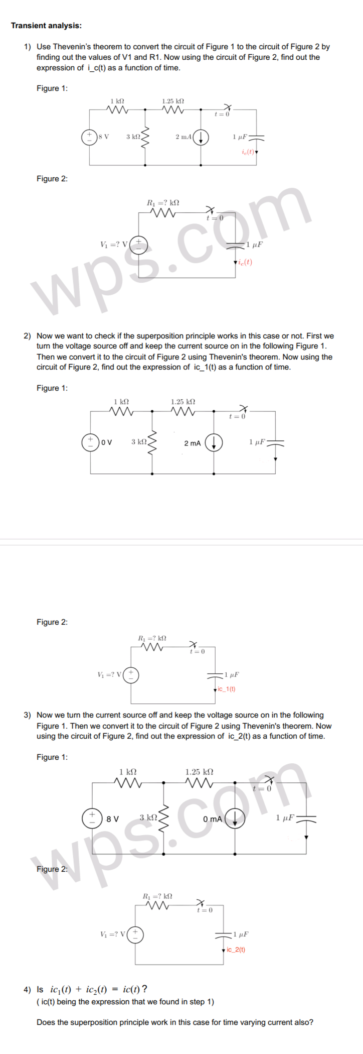
Transcribed Image Text:Transient analysis:
1) Use Thevenin's theorem to convert the circuit of Figure 1 to the circuit of Figure 2 by
finding out the values of V1 and R1. Now using the circuit of Figure 2, find out the
expression of i_c(t) as a function of time.
Figure 1:
1 k!
1.25 k?
t = 0
3 kN.
2 mA
1 µF-
i(t)
Figure 2:
R1 =? kN
t=0
Vị =? V
1 µF
vi(t)
wps.com
2) Now we want to check if the superposition principle works in this case or not. First we
turn the voltage source off and keep the current source on in the following Figure 1.
Then we convert it to the circuit of Figure 2 using Thevenin's theorem. Now using the
circuit of Figure 2, find out the expression of ic_1(t) as a function of time.
Figure 1:
1 k
1.25 ko
t= 0
ov
3 kN
2 ma ()
1 µF
Figure 2:
R1 =? k£!
t =0
V =? V
1 µF
v ic_1(t)
3) Now we turn the current source off and keep the voltage source on in the following
Figure 1. Then we convert it to the circuit of Figure 2 using Thevenin's theorem. Now
using the circuit of Figure 2, find out the expression of ic_2(t) as a function of time.
Figure 1:
1 kN
1.25 k?
8 V
3 kN.
O mA
1 µF
Figure
R1 =? k?
t= 0
Vị =? V
1 µF
v ic_2(t)
4) Is ic¡(t) + ic,(t) = ic(t)?
( ic(t) being the expression that we found in step 1)
Does the superposition principle work in this case for time varying current also?
Expert Solution
This question has been solved!
Explore an expertly crafted, step-by-step solution for a thorough understanding of key concepts.

This is a popular solution!

Trending now
This is a popular solution!

Step by step
Solved in 8 steps with 8 images

Knowledge Booster


Learn more about
Need a deep-dive on the concept behind this application? Look no further. Learn more about this topic, electrical-engineering and related others by exploring similar questions and additional content below.Recommended textbooks for you
Introductory Circuit Analysis (13th Edition)
Electrical Engineering
ISBN:
9780133923605
Author:
Robert L. Boylestad
Publisher:
PEARSON

Delmar's Standard Textbook Of Electricity
Electrical Engineering
ISBN:
9781337900348
Author:
Stephen L. Herman
Publisher:
Cengage Learning

Programmable Logic Controllers
Electrical Engineering
ISBN:
9780073373843
Author:
Frank D. Petruzella
Publisher:
McGraw-Hill Education
Introductory Circuit Analysis (13th Edition)
Electrical Engineering
ISBN:
9780133923605
Author:
Robert L. Boylestad
Publisher:
PEARSON
Delmar's Standard Textbook Of Electricity
Electrical Engineering
ISBN:
9781337900348
Author:
Stephen L. Herman
Publisher:
Cengage Learning
Programmable Logic Controllers
Electrical Engineering
ISBN:
9780073373843
Author:
Frank D. Petruzella
Publisher:
McGraw-Hill Education

Fundamentals of Electric Circuits
Electrical Engineering
ISBN:
9780078028229
Author:
Charles K Alexander, Matthew Sadiku
Publisher:
McGraw-Hill Education

Electric Circuits. (11th Edition)
Electrical Engineering
ISBN:
9780134746968
Author:
James W. Nilsson, Susan Riedel
Publisher:
PEARSON

Engineering Electromagnetics
Electrical Engineering
ISBN:
9780078028151
Author:
Hayt, William H. (william Hart), Jr, BUCK, John A.
Publisher:
Mcgraw-hill Education,