UFMFH3-30-1 Problem Sheet 2 Calculate the reactions at the supports of the simply supported beams with UDLS shown below Question 1 20 kN UDL = 5 kN/m D lm 1m 2m RA RD Question 2 4.5 kN UDL = 2 kN/m B 1.25 m 1.5 m 2.5 m Question 3 20 kN 15 kN| UDL = 5 kN/m Im 2m 3m lm 3m Question 4 10 kN | 20 kN UDL = 20 kN/m D A 2.5m 2m 2m 3m RBY REY 16
Q: I'm stuck with the attached problem. Can anyone please provide step by step solution with the FBD…
A: Consider the free body diagram of the structure. Due to the roller support at point B only vertical…
Q: Answer FOUR questions ONLY selecting TWO questions from SECTION A. 1. (a) The vertical structure…
A: Find the reaction at point A and stress in steel bar and aluminium tube.
Q: let d={{.006, .002, .001},{.002, .004, .002},{.001, .002, .006}} be a flexibility matrix, with…
A:
Q: C a b a Nb! Fd = 21 KN Alfa= 20 a) Find reactions forces, shear and normal forces and torque for the…
A: Draw the free-body diagram of the beam. Apply force equilibrium in a x-direction. Bx=0 Apply…
Q: 13. For the same Figure in Problem 11, the reaction at the fixed support B is- a. 645 N-m (CW) b.…
A: Torque given are 800 Nm and 500 Nm. Diameter of the shaft, d= 20 mm= 0.02 m
Q: 616. For the beam loaded as shown in Fig. P-616, determine (a) the deflection and slope under the…
A: solution to Problem 617 as mentioned by the student.
Q: Question 7- SFD & BMD - Simply Beam (UDL) UDL = 6 kN/m 8 m i) Draw the Free-Body Diagram & Find…
A:
Q: 152 x 152 x 23 UC Frame Beam Diagram 28.2KN Self Load 805N 28.2KN 2.0m Ra 75 3.5m Pulley and Shaft…
A: find the reactions at the supports.
Q: The A-36 steel rod BC as shown in Figure Q3 has a diameter of 54 mm and is used as a strut to…
A: For solution refer below images.
Q: The beam shown in Figure P5.8-3 is a W16x31 of A99 steel and has continuous lateral support. The two…
A:
Q: Q3\\ Answer with True or False of the following question:( 1.The slope of the moment diagram at a…
A: 1. "The slope of moment diagram" at any given point gives the magnitude of shear force at that…
Q: 13-34. Forces are applied on a rigid frame as shown in Figure 13-60. Find the reactions at A and B.…
A:
Q: Determine the axial load at point B for the beam below. 12 k 60° B 8k Lsntsnsnsn -5 ft- Select the…
A: GIVEN DATA- A CANTILEVER BEAM GIVEN LOADED WITH POINT LOAD WE HAVE TO FIND AXIAL FORCE AT B
Q: The deflection at x = 3L/4 is Select one: -17wL 384EI Oa. -513wL 6144EI
A:
Q: A pulley 1.2 m in diameter and supporting a load of 900 N is mounted at B on a horizontal beam…
A:
Q: An inclined steel bar 2 m long, having a cros section of 4000 mm² and an I of 8.53 x 10 mm, is…
A:
Q: Statics and Equilibrium Draw and label a complete FBD of each beam Solve for the reaction forces…
A:
Q: A 33 m beam has two supports. It overhangs each support by 5 m. The beam carries a point load of 600…
A: Draw the beam according to the question.
Q: Uniformly distributed load of 5 kN acts on a simply supported beam of length 10 m. What are the…
A:
Q: -3 kN/m
A:
Q: Repeat Prob. 15-7 if the dead load reaction is 80 k and the live load reaction is 110 k, and if 1-in…
A:
Q: YES OR NO Case P1. A 10m beam is loaded with point load P1 = 100N at 2m from the fixed end support.…
A: We know if number of unknown reactions is equal to number of equations of equilibrium, the structure…
Q: 3-6. A simply supported beam 6m long is carrying a uniformly distributed load of 5kN/ m over a…
A: given; distributed load(w)=5KN/m
Q: 200 kN/m 140 kN I (m) 5 10 7.5 Figure.2: Encastré beam under variety of loads Your tasks are as…
A:
Q: use EI constant for whole span). A 10-meter-span, propped beam (fixed at the left support and…
A:
Q: Compute the midspan value of EI 8 for the beam loaded as shown in Figure. 600 N/m 3 m 2 m R₁ Figure…
A:
Q: a) What is the importance of SFD and BMDs for structural engineers? b) For the beam and loading…
A:
Q: A simply supported beam of length 7m is carrying a uniformly distributed load of 1.25N/m for its…
A: Given Length, l = 7m Uniformly distributed load, w = 1.25N/m Find…
Q: Draw the Shear Force Diagram (SFD) and Bending Moment Diagram (BMD) for a loaded simply supported…
A: Given data To draw the shear force and bending moment diagrams of the give nsimply supported beam
Q: The static transverse deflection of simply supported beam with a uniformly distributed load (UDL)…
A:
Q: Draw the free-body diagram of the uniform beam shown in Fig. 5-7a.
A:
Q: 8 kN/m B -4m - -2 m-
A:
Q: pulley I =10mr? rigid, massless link. 3m
A: Given,
Q: Original problem: Set up equations needed to determine moments acting an function of flexural…
A: to find moments
Q: When a 75mm X 100mm simply supported 6 m simply supported beam with a concentrated load of 100 KN…
A: It is required to determine value of maximum moment
Q: Question 5 a) What is the importance of SFD and BMDs for structural engineers? b) For the beam and…
A:
Q: 3- Draw the shear force and bending moment of the beam. You have to find their equation, and your…
A:
Q: Question # 2: Draw shear force and bending moment diagram for beam below. 10 Nm 25 kNm 1 m 1 m 3 m…
A: First step is to find the reactions at two given supports by drawing free body diagram of beam. Then…
Q: SITUATION 1: A T-beam is simply supported and is used to carry a uniform load of 20 kN/m. The beam…
A: Shear stress force tends to cause deformation of a material by slippage along a plane or planes…
Q: What is most nearly the reaction force at support B on the simply supported beam with a linearly…
A:
Q: A uniform beam weighing 50 lbs and 12 ft long leans against a smooth wall with its lower end 6 ft…
A: The distance between the base of beam and the wall is 6 feet and the length of the beam is 12 feet.…
Q: Draw the Shear Force Diagram (SFD) and Bending Diagram (BMD) for a loaded simply supported beam…
A: Consider the free body diagram of the beam as shown below. From the moment equilibrium about the…
Q: Name: Date: Courset Time: 2. A Rigid beam with negligible mass is pinned at one end and suppoRted by…
A:
Q: am 15kN 35 3m IDKN am Initial FBD Final FBD Find the reactions. Fill in the blank's Draw and label…
A:
Q: 12-3. Determine the forces in the members of the Fink truss in Figure 12-13. 4 k 4 k 4k 10 ft 2k 2k…
A:
Q: The turbine motor moving at 378 rev/ min can produce 2.5 hp. The shaft diameter is 1.25 inches.…
A: Given data: The diameter of the shaft is d = 1.25 inchThe speed of the turbine rotor is N = 378…
Q: The static transverse deflection of simply supported beam with a uniformly distributed load (UDL) is…
A: Answer is (b) 5wl4 /384EI
Q: Q3: If the figure (2) below shows a bending moment diagram (B.M.D) for the beam CABD, then the load…
A: On the beam the slope created when the load act on the beam is point load and the parabolic curve…
please could you do the shear force diagram for question 2
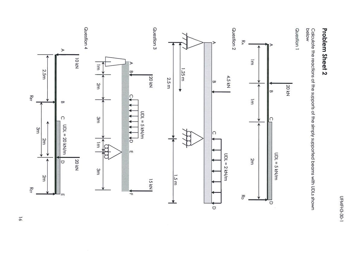
Step by step
Solved in 2 steps with 3 images
- A flying but tress transmit s a load P = 25 kN, acting at an angle of 60º to the horizontal, to the top of a vertical buttress AB (see figure). The vertical buttress has height h = 5.0 m and rectangular cross section of thickness t = 1.5 m and width b = 1.0 m (perpendicular to the plane of the figure). The stone used in the construction weighs y = 26 kN/m3. What is the required weight W of the pedestal and statue above the vertical buttress (that is, above section A) to avoid any tensile stresses in the vertical buttress?Question 1) in FIG loading condition is given beam F force F = 65 kN , first distributed load W 1 = 41 kN / m , w 2 distributed load w 2 = 51 kN / m , θ angle θ = 48 ° and L length of L = 5 m . According to this; Question 1-A) B at the point y direction ( B y ) Determine the support reactions. (Enter yourresultwithout writing kN units.) Question 1-B) to the point in y direction ( A y ) Determine the support reactions. ( Enter yourresult without writing kN units.) Question 1-C) to the point in x direction ( A x ) Determine the support reactions. ( Enter yourresult without writing kN units.)The given beam in Fig. P9-22 is A992 steel. If the live load is twice the dead load, what is the maximum total service load in k/ft that can be supported when (a) the compression flange is braced laterally for its full length, and (b) lateral bracing is supplied at the ends and centerline only?
- A simply supported steel universal I shaped beam is shown(see attached table and choose one size) The total length is 15 meters with a concentrated force P (located at a distance a = 10 meters) created by a mass of 2000 kg. By assuming a yield strength of 350 MPa and a safety factor of 3.2 state the ergonomically suitable nominal beam size from the catalogue. With reference to answer describe the type of beam failure and at least one possible consequence if the I-beam size you selected is too small. You may add additional images for illustration purposes but ensure that (a) it is described properly, and (b) it is relevant.26 - Support reactions will be found in the gerber beam whose loading condition is given in the figure. A is the fixed support, the G point is the intermediate joint, and the B support is the sliding joint. Distributed loads on the beam q1= 9 kN ⁄ m, q2= 6 kN ⁄ m, beam dimensions a = 3 m, b = 2 m. Accordingly, Bx = ?A) 19.5B) 6C) 0D) 45E) None.The plate shown is made of UNS G10350 cold drawn steel (Sy=460 MPa and Su=550 MPa),and is fastened to an I beam made of UNS G10150 cold drawn steel (Sy=320 MPa and Su=385 MPa) by four rivets made of a steel with Sy=300 MPa and Su=365 MPa. Thickness of the plate is 10 mm and thickness of the flanges of the I beam is 15 mm. Diameter of the rivets is 20 mm. What safe load F (steady) can be supported by the riveted joint for a factor of safety of 2. Use distortion energy theory of failure.
- Given the following properties of a rectangular concrete beam: b = 280mm, d = 480 mm, f'c = 21 MPa, fy = 414 MPa. The beam is reinforced for tension only. Determine the design strength under the following conditions. a.) When the beam is reinforced with three 25 mm diameter bars. b.) When the beam is reinforced with four 25 mm diameter bars. c.) When the beam is reinforced with seven 25 mm diameter bars.Şekildeki ankastre kompozit kiriş çelik ve alüminyumdan üretilmiş olup ucuna 20 kN’luk bir kuvvet uygulanmıştır. Verilenlere göre çelik ve alüminyumda oluşan maksimum gerilmeleri bulunuz. (Eç=200 GPa, EAl=80 GPa) The recessed composite beam in the figure is made of steel and aluminum and a force of 20 kN is applied to its end. Find the maximum stresses in steel and aluminum according to the givenPage422, Concept Problem 6.1. Solve this problem completely,butwith the following changes. (1) Continue toassume that the upper plank is 100 mm wide. (2) Assumenowthat the lower plank isreduced to80 mm wide. (3)Assume that each nail shouldwithstand ashearingforce of no more than 100 N.The questions are: (a) What is therequired spacing of the nails in the upper plank? (b) What is the required spacing of the nails in the lower plank?Please keep in mind that thesechangeswill result in many other changes across the board. Discuss all practicalissues in your findings.
- A weight of 1200N is dropped vertically at the middle of a beam 50mmx250mm and 6m long simply supported at both ends. At what height must the weight be dropped so as to cause a stress of 14MPa in the beam? E = 8200MPa. See figure 09.Tc = ? (shear stress)c= ?In the beam, which is given the loading and supporting status below a) Find the location of the largest crash and the value of the crash. b) What is the maximum length of the beam (L) so that the largest collapse value is less than 1.5 mm? E = 210 GPa Mo = 250 kNm I = 556x10-6 m4