Use the following state diagram and create the state table for a synchronous to detect the sequence. The circuit has a single input, x, and a single output z. The output is logic-1 whenever the input sequence 1001 is detected, logic-0 otherwise. Note that overlapping sequences are allowed, Create the initial state table, and the complete state table. Write the equations for all the state variables and the output z. 1 so S1 S2 S3 Z=0 Z=1 State diagram of 1001 sequence recognizer
Use the following state diagram and create the state table for a synchronous to detect the sequence. The circuit has a single input, x, and a single output z. The output is logic-1 whenever the input sequence 1001 is detected, logic-0 otherwise. Note that overlapping sequences are allowed, Create the initial state table, and the complete state table. Write the equations for all the state variables and the output z. 1 so S1 S2 S3 Z=0 Z=1 State diagram of 1001 sequence recognizer

Chapter22: Sequence Control
Section: Chapter Questions
Problem 6SQ: Draw a symbol for a solid-state logic element AND.

Related questions
Question
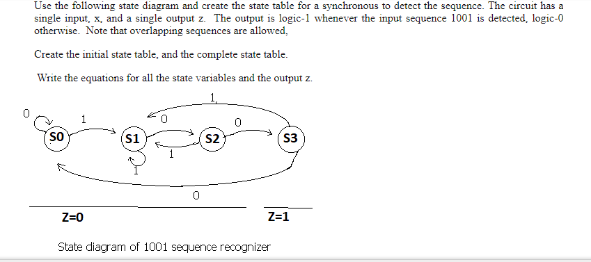
Transcribed Image Text:Use the following state diagram and create the state table for a synchronous to detect the sequence. The circuit has a
single input, x, and a single output z. The output is logic-1 whenever the input sequence 1001 is detected, logic-0
otherwise. Note that overlapping sequences are allowed,
Create the initial state table, and the complete state table.
Write the equations for all the state variables and the output z.
1
so
S1
S2
S3
Z=0
Z=1
State diagram of 1001 sequence recognizer
Expert Solution
This question has been solved!
Explore an expertly crafted, step-by-step solution for a thorough understanding of key concepts.

This is a popular solution!

Trending now
This is a popular solution!

Step by step
Solved in 2 steps with 2 images

Knowledge Booster


Learn more about
Need a deep-dive on the concept behind this application? Look no further. Learn more about this topic, electrical-engineering and related others by exploring similar questions and additional content below.Recommended textbooks for you