Using the method of joints, calculate the force in each member of the truss shown below. State whether each member is in tension or compression. Use Method of Joints.
Using the method of joints, calculate the force in each member of the truss shown below. State whether each member is in tension or compression. Use Method of Joints.

International Edition---engineering Mechanics: Statics, 4th Edition
4th Edition
ISBN:9781305501607
Author:Andrew Pytel And Jaan Kiusalaas
Publisher:Andrew Pytel And Jaan Kiusalaas
Chapter5: Three-dimensional Equilibrium
Section: Chapter Questions
Problem 5.26P: The figure shows the FBD of a portion of the space truss shown in Fig. P5.25. Use this FBD to find...

Related questions
Question
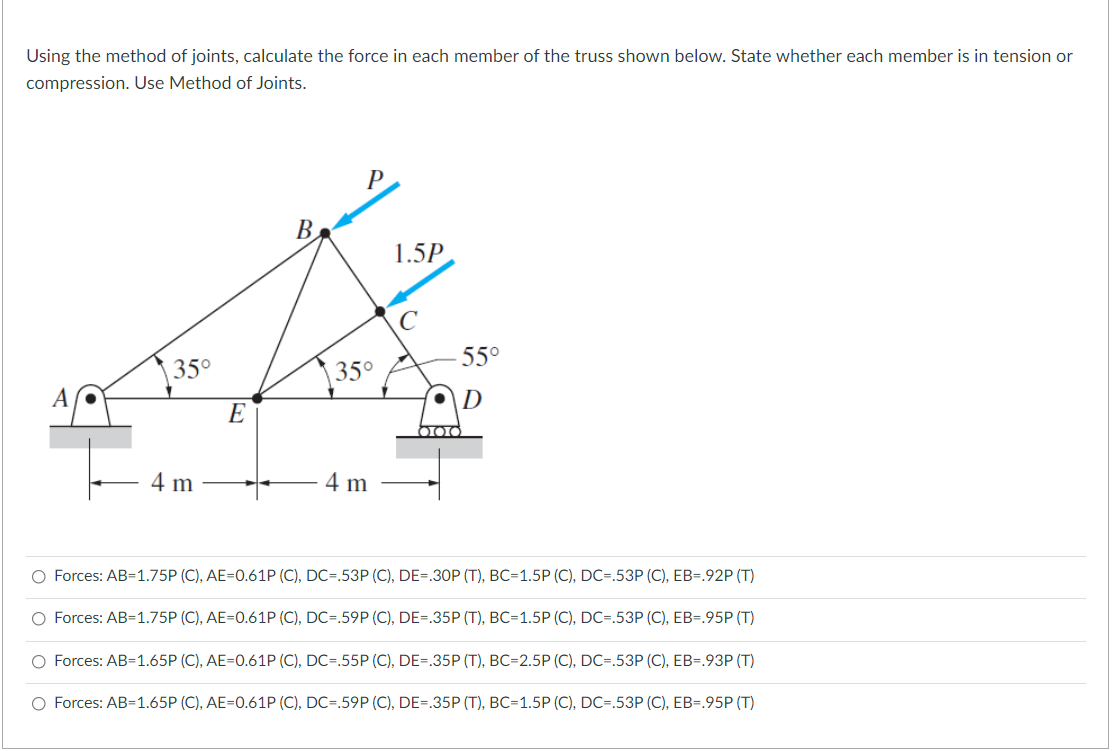
Transcribed Image Text:Using the method of joints, calculate the force in each member of the truss shown below. State whether each member is in tension or
compression. Use Method of Joints.
P
B.
1.5P
55°
35°
35°
D
E
4 m
4 m
O Forces: AB=1.75P (C), AE=0.61P (C), DC=.53P (C), DE=.30P (T), BC=1.5P (C), DC=.53P (C), EB=.92P (T)
O Forces: AB=1.75P (C), AE=0.61P (C), DC=.59P (C), DE=.35P (T), BC=1.5P (C), DC=.53P (C), EB=.95P (T)
O Forces: AB=1.65P (C), AE=0.61P (C), DC=.55P (C), DE=.35P (T), BC=2.5P (C), DC=.53P (C), EB=.93P (T)
O Forces: AB=1.65P (C), AE=0.61P (C), DC=.59P (C), DE=.35P (T), BC=1.5P (C), DC=.53P (C), EB=.95P (T)
Expert Solution
This question has been solved!
Explore an expertly crafted, step-by-step solution for a thorough understanding of key concepts.

This is a popular solution!

Trending now
This is a popular solution!

Step by step
Solved in 5 steps with 5 images

Recommended textbooks for you
International Edition---engineering Mechanics: St…
Mechanical Engineering
ISBN:
9781305501607
Author:
Andrew Pytel And Jaan Kiusalaas
Publisher:
CENGAGE L
International Edition---engineering Mechanics: St…
Mechanical Engineering
ISBN:
9781305501607
Author:
Andrew Pytel And Jaan Kiusalaas
Publisher:
CENGAGE L