Calculate the force in each truss member using the method of joints, and state hi initial
Calculate the force in each truss member using the method of joints, and state hi initial

Mechanics of Materials (MindTap Course List)
9th Edition
ISBN:9781337093347
Author:Barry J. Goodno, James M. Gere
Publisher:Barry J. Goodno, James M. Gere
Chapter7: Analysis Of Stress And Strain
Section: Chapter Questions
Problem 7.6.11P: -11 A rubber cube R of a side L = 3 in. and cross- sectional area A = 9 in2 is compressed inside a...

Related questions
Question
Answer
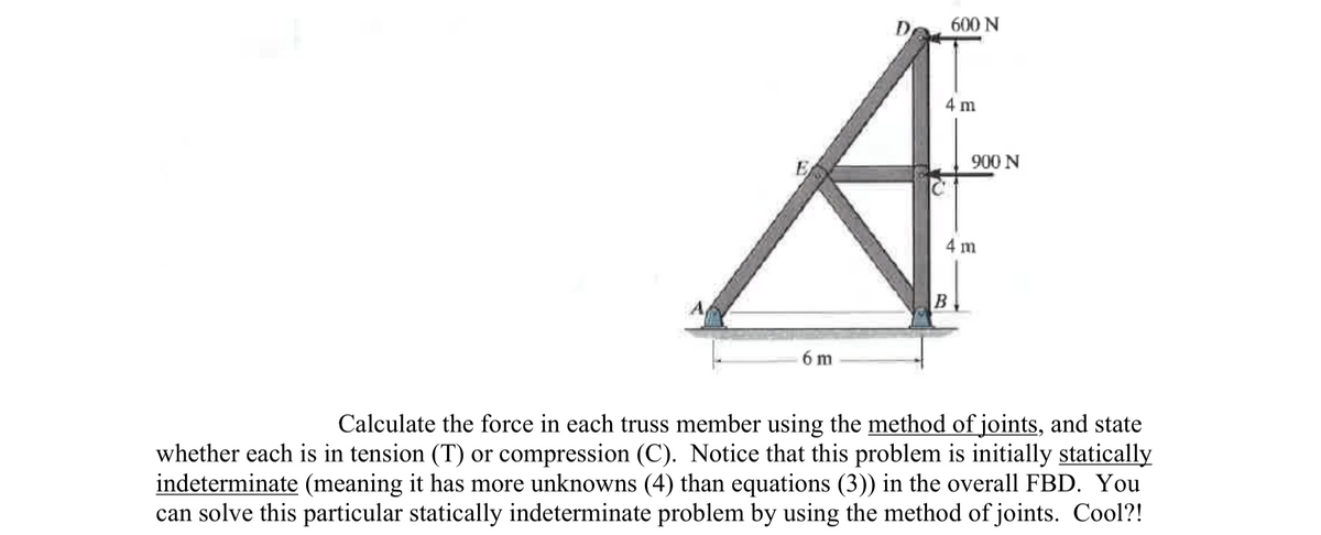
Transcribed Image Text:600 N
4 m
900 N
4 m
6 m
Calculate the force in each truss member using the method of joints, and state
whether each is in tension (T) or compression (C). Notice that this problem is initially statically
indeterminate (meaning it has more unknowns (4) than equations (3)) in the overall FBD. You
can solve this particular statically indeterminate problem by using the method of joints. Cool?!
Expert Solution
This question has been solved!
Explore an expertly crafted, step-by-step solution for a thorough understanding of key concepts.

Step by step
Solved in 4 steps with 4 images

Knowledge Booster


Learn more about
Need a deep-dive on the concept behind this application? Look no further. Learn more about this topic, mechanical-engineering and related others by exploring similar questions and additional content below.Recommended textbooks for you
Mechanics of Materials (MindTap Course List)
Mechanical Engineering
ISBN:
9781337093347
Author:
Barry J. Goodno, James M. Gere
Publisher:
Cengage Learning
Mechanics of Materials (MindTap Course List)
Mechanical Engineering
ISBN:
9781337093347
Author:
Barry J. Goodno, James M. Gere
Publisher:
Cengage Learning