Value 1) Req 2) Veg 3) IB 4) IE 5) Ic 6) VCE 7) VE 8) VB 9) re 10) 9m 11) T 12) Zin 13) Zout 14) Vaut 15) Av (12+12/25 ^-1 R1 R2 R1 + R2 (B+1) * IB IB* B -Veg+ Req*IB+ Vbe +Re [ (ß +1) *IB]=0 IE*RE VBE+VE VT IE (IC) * Vcc -VCC+ VCE+RC (IC) +RE (IE) = 0 (VT) (B) (9m) Rin= Rout= -ß (B+1) Vout Vsig (rn) (B+1) Table 3 RC (RL) Equations RC+(RL) -Rin Rin+Rsig re RC (RL). (Vsig) (RC+(RL) Final Value
Value 1) Req 2) Veg 3) IB 4) IE 5) Ic 6) VCE 7) VE 8) VB 9) re 10) 9m 11) T 12) Zin 13) Zout 14) Vaut 15) Av (12+12/25 ^-1 R1 R2 R1 + R2 (B+1) * IB IB* B -Veg+ Req*IB+ Vbe +Re [ (ß +1) *IB]=0 IE*RE VBE+VE VT IE (IC) * Vcc -VCC+ VCE+RC (IC) +RE (IE) = 0 (VT) (B) (9m) Rin= Rout= -ß (B+1) Vout Vsig (rn) (B+1) Table 3 RC (RL) Equations RC+(RL) -Rin Rin+Rsig re RC (RL). (Vsig) (RC+(RL) Final Value

Introductory Circuit Analysis (13th Edition)
13th Edition
ISBN:9780133923605
Author:Robert L. Boylestad
Publisher:Robert L. Boylestad
Chapter1: Introduction
Section: Chapter Questions
Problem 1P: Visit your local library (at school or home) and describe the extent to which it provides literature...

Related questions

Question
Solve 10,11,12
![Value
1) Req
2) Veg
3) IB
4) IE
5) Ic
6) VCE
7) VE
8) VB
9) re
10) 9m
11) T
12) Zin
13) Zout
14) Vaut
15) Av
(₁ + 2/2)^-1
R2
R2
R1 + R2
(ß + 1) * IB
IB* B
-Veq+ Req*IB+ Vbe +Re [ (ß +1) *IB]=0
IE*RE
VBE+VE
* Vcc
-VCC+ VCE+RC (IC) +RE (IE) = 0
VT
IE
(IC)
(VT)
(B)
(9m)
Rin=
Vout
Vsig
(rn)
(B+1)
RC (RL)
Rout=
-B
(B+1) Rin+Rsig
Table 3
Equations
RC+(RL)
-Rin
(Vsig)
RC* (RL)
RC+(RL)
Final Value](/v2/_next/image?url=https%3A%2F%2Fcontent.bartleby.com%2Fqna-images%2Fquestion%2Fa7cf143d-c2c6-4213-971b-95909956e40e%2Fd966b259-1f22-4ea3-a9b8-e038bd87ac44%2F6von5m8_processed.jpeg&w=3840&q=75)
Transcribed Image Text:Value
1) Req
2) Veg
3) IB
4) IE
5) Ic
6) VCE
7) VE
8) VB
9) re
10) 9m
11) T
12) Zin
13) Zout
14) Vaut
15) Av
(₁ + 2/2)^-1
R2
R2
R1 + R2
(ß + 1) * IB
IB* B
-Veq+ Req*IB+ Vbe +Re [ (ß +1) *IB]=0
IE*RE
VBE+VE
* Vcc
-VCC+ VCE+RC (IC) +RE (IE) = 0
VT
IE
(IC)
(VT)
(B)
(9m)
Rin=
Vout
Vsig
(rn)
(B+1)
RC (RL)
Rout=
-B
(B+1) Rin+Rsig
Table 3
Equations
RC+(RL)
-Rin
(Vsig)
RC* (RL)
RC+(RL)
Final Value
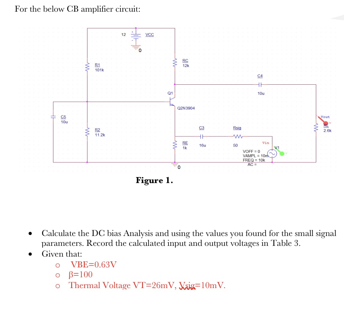
Transcribed Image Text:For the below CB amplifier circuit:
C5
10u
R1
101k
R2
11.2k
12
VBE=0.63V
AIHE
0
VCC
ww
Q1
www
Figure 1.
RC
12k
Q2N3904
0
RE
1k
C3
HI
16u
Rsig
0 B=100
Thermal Voltage VT=26mV, Vsig=10m V.
50
C4
HH
10u
Vin
VOFF = 0
VAMPL = 10m
FREQ = 10k
AC =
V1
Vout
Calculate the DC bias Analysis and using the values you found for the small signal
parameters. Record the calculated input and output voltages in Table 3.
Given that:
2.6k
Expert Solution
This question has been solved!
Explore an expertly crafted, step-by-step solution for a thorough understanding of key concepts.

Step by step
Solved in 4 steps with 3 images

Knowledge Booster


Learn more about
Need a deep-dive on the concept behind this application? Look no further. Learn more about this topic, electrical-engineering and related others by exploring similar questions and additional content below.Recommended textbooks for you
Introductory Circuit Analysis (13th Edition)
Electrical Engineering
ISBN:
9780133923605
Author:
Robert L. Boylestad
Publisher:
PEARSON

Delmar's Standard Textbook Of Electricity
Electrical Engineering
ISBN:
9781337900348
Author:
Stephen L. Herman
Publisher:
Cengage Learning

Programmable Logic Controllers
Electrical Engineering
ISBN:
9780073373843
Author:
Frank D. Petruzella
Publisher:
McGraw-Hill Education
Introductory Circuit Analysis (13th Edition)
Electrical Engineering
ISBN:
9780133923605
Author:
Robert L. Boylestad
Publisher:
PEARSON
Delmar's Standard Textbook Of Electricity
Electrical Engineering
ISBN:
9781337900348
Author:
Stephen L. Herman
Publisher:
Cengage Learning
Programmable Logic Controllers
Electrical Engineering
ISBN:
9780073373843
Author:
Frank D. Petruzella
Publisher:
McGraw-Hill Education

Fundamentals of Electric Circuits
Electrical Engineering
ISBN:
9780078028229
Author:
Charles K Alexander, Matthew Sadiku
Publisher:
McGraw-Hill Education

Electric Circuits. (11th Edition)
Electrical Engineering
ISBN:
9780134746968
Author:
James W. Nilsson, Susan Riedel
Publisher:
PEARSON

Engineering Electromagnetics
Electrical Engineering
ISBN:
9780078028151
Author:
Hayt, William H. (william Hart), Jr, BUCK, John A.
Publisher:
Mcgraw-hill Education,