VD1 - A 9:2 V = 240 Vms + Kpi RL . V. B 
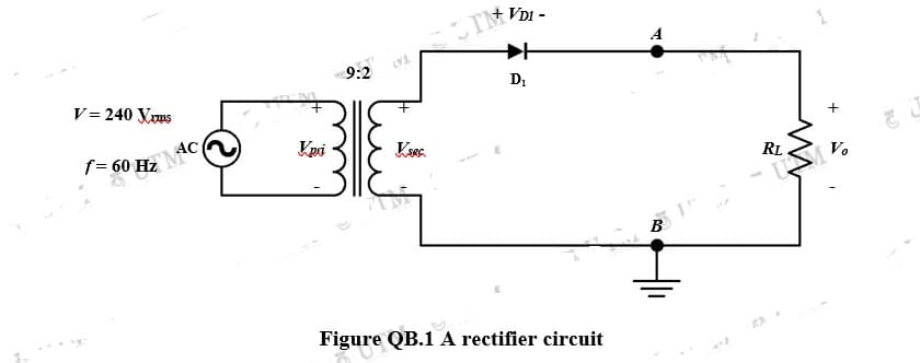
Figure QB.1 A rectifier circuit
Q: Derive the truth table, simplified equation, and logical diagram 1. Design a 4-bit majority…
A: Since you have asked multiple question, we will solve the first question for you. If you want any…
Q: 1. Sketch the output waveform of the given circuit in Figure 1. The peak voltage is 20V with 50HZ…
A: Given: V=20V
Q: find the transfer function G(s) of the translational mechanical system below
A:
Q: What is the total inductive reactance of a 4 mH coil connected to a 1000 Hz source? 6. Your Answer:…
A: The solution is given below
Q: imple capacitors
A: Capacitor- A device consisting of parallel pair of conducting plates separated with some…
Q: 6. The efficiency of DC to DC converter to drive de motor is -- than AC to DC Drives a) Inwer b)…
A: 6. The efficiency of DC to DC converter to drive DC motor is higher than AC to DC drives. Option C…
Q: Determine Vo for each of the circuit below. 4 V 2.2 k2 +8 V 2.2 ka (a) (b)
A: For the given circuits calculation of output voltage V0 . We know, For Si diode: When Diode in FB…
Q: Find the operating region of the MOSFET and Vp when I, = 0.2A and R=5 ohm? %3D +1.8 V o VD O a.…
A: Brief description : MOSFET is a transistor which is widely used as amplifier circuits. Generally…
Q: How to solve for a (+) Phase Sequence and (-) Phase Sequence? Give an example and explain the steps.
A: When a unsymmetrical fault occurs in the system then system becomes unbalanced. To understand the…
Q: 4. Find the period, frequenay, and the amplitude of the current wave form shown below. 2 +t, ms 10…
A: We need to find out amplitude , frequency ,time period.
Q: 15 Determine the voltage across resistor R2. (assume Zener voltage is 3 volts) * R2 1K R1 10V D2 1K
A:
Q: Z1= 2+J5 is connected to a parallel combination of Z2=5 ohms ; Z3= j2 ohms and Z4 = 3-j4 ohms.…
A: The solution is given below
Q: 5. The bridge rectifier shown in Figure 2 uses ideal diodes. The input voltage is 24V. Find: a. DC…
A:
Q: Determine the current flowing through the LED. (assuming its forward voltage is 2.1 volts and diode…
A:
Q: 6 Determine the voltage across the resistor R1. (assume LED forward voltage is 2.1 volts) * A D1 R1…
A: The solution is given below
Q: sign a clamper to perform the function indicated below. Silicon diodes 10 V 2.7 V -10 V -17.3 V
A: Please refer the attached images for the complete answer..
Q: State the definition of open loop and closed loop systems.
A: Defination of open loop and closed loop control system:
Q: X(s) 2K C(s) 1 s(s + 5) (0) Find the closed-loop transfer function of the system in terms of K.
A: Given,
Q: 1 R2 1K R1 5V D1 1K Determine the voltage across the resistor R2. (assume LED forward voltage is 2.1…
A:
Q: 1. Design a 4-bit combinational circuit that adds one (1) to the input if the input is less than…
A: As per our guidelines we are supposed to be answer the first question only kindly repost the other…
Q: 1. Sketch the output waveform of the given circuit in Figure 1. The peak voltage is 20V with 50HZ…
A: In this question, We need to draw the output voltage waveform if diode is ideal and si type.…
Q: mpedances Z1=5.83<-59 and Z2=8.94<63.43 are in series and carry and effective current of 5.0 A.…
A:
Q: olve for the voltage drop and the power dissipated across resistance R3 using Nodal Analysis. ww. 34…
A:
Q: Determine the voltage across the resistor R1 if the Zener Voltage is 4.7 V * R2 1K R1 5V D2 1K
A: In this question, We need to determine the voltage across the resistor R1 if the Zener Voltage is…
Q: 24 V 12 N 56 N 8 A 24 2
A: We need to find current for given circuit.
Q: which among these is the divergence function
A:
Q: Q3: Find the h-parameters for the two-port network shown in Figure 2. 1, 30 0.5V, V, 312
A: In this question, We need to determine the h parameters of the given circuit?
Q: R= 180 2 120 V 30 mH 1000 Hz coil Solve for total circuit Z. Copy paste these in as needed 2° (No…
A: The solution is given below
Q: Determine the current at the resistor R1. (assume LED forward voltage is 2.1 volts and Diode forward…
A: In this question, We need to determine the current at the resistor R1. (assume LED forward…
Q: C(s) s+2 2. G(s) = R(s) Write the state matrix s2+4s+3 equation and the output equation in the phase…
A: Brief description : In the above given question they have mentioned transfer function of the system.…
Q: For the circuit below, solve for the current at 6-N resistor using Superposition Theorem. lov (+ t)…
A:
Q: (а) A•B (b) A×B (с) Өдв between A and B АВ
A:
Q: 16 Determine the current at LED, D2. (assume LED forward voltage is 2.1 volts) * R2 1K 5V D1 R1 D2
A: The solution is given below
Q: The 555 timer is connected in the following circuit. The resistance of the extra resistor is 102,…
A: Since you have posted a question with multiple sub-parts, we will solve the first three subparts for…
Q: Derive the time response v,(t) for the circuit given in Figure Q3. Where, v(t) is a step signal. Q3
A:
Q: Find Yoltoge accross nodes 1 and 2 = Viz 552 252 1052 IA $552
A:
Q: Two identical three – phase Y – connected alternator A and B share equally a load of 10MW at 33kV…
A:
Q: Vec v Find VAB E Ver BC 360L 150 I Ct) Sequenae z L-) Seqpuen ce
A:
Q: Calculate v, in the circuit of Fig. 10.15 using the superposition theorem. ww 75 sin 51 V 0.2 F 6…
A:
Q: FIND THE THEVENIN EQUIVALENT Vx 1 ΚΩ 2 kN 1 kN A +)2Vx 2 kN 1 kN В
A: In this question, We need to determine the Thevenin equivalent theorem. In this circuit, no…
Q: Q.32: The two-wattmeter method gives P1=1200W and P2=-400W for 3-Ph motor running on 240V line.…
A: The solution is given below
Q: The length of one cycle of an electromagnetic wave in space is referred to as its wavelength. The…
A:
Q: 22 Determine the voltage across the resistor R2. (assume Zener voltage is 3 volts and Diode forward…
A: The solution is given below
Q: Find the Q-point values for the JFET with voltage-divider bias. IDss = 5 mA Vpp +12 V Rp 1.8 kN 3.3…
A:
Q: 5. The bridge rectifier shown in Figure 2 uses ideal diodes. The input voltage is 24V. Find: DC…
A: In this question bridge rectifier is given...We have to find out dc output voltage and output…
Q: 12 I1 I2 15V 52 5V
A:
Q: 6. What is the other name for PWM? 7. What is the disadvantage of PWM? 8. Will PWM work if the…
A: Answer :- The other name of Pulse width modulation (PWM) is Pulse Duration Modulation (PDM). This…
Q: Question: How strongly does the output voltage drop under load in comparison with no-load? What are…
A: Voltage It is a electrical term which defines the change in potential difference i.e voltage , due…
Q: 1. Consider the circuit in the intro video in UVLE as shown in the circuit below +12V Rq=12K R2 The…
A: Given: Consider the following circuit: The light-dependent resistor (LDR) R2 is: R2=1 MΩ⇒When it is…
Q: JQ K Qt FFO D- K of FF1
A: Sequential circuits are logical circuits consisting of input, output, and logic gates. A state table…
Step by step
Solved in 3 steps with 2 images
- What is CEMF?Explain the given circuit diagram and also explain its functions with suitable examples. Rubrics: Explain the functions of given IC function(s) with suitable example. Write down the formula for charging, discharging time and the frequency.Half-wave 60Hz sinusoidal uncontrolled rectifier circuit with a peak voltage value of 100V and a source inductance of 8mH is feeding a highly inductive load of 8A. The average value of the output voltage and power delivered are, respectively and what is the communication angle (u) (Power Electronics)
- Subject : Electronics Engineering A silicon diode having 20 Ω internal resistance is used as half wave rectifier. If the applied input voltage is 50 sin100πt and load resistance is 800 Ω, then finda) Im, Idc and Irmsb) Output frequency and ripple factorc) AC input and output power d) efficiencyDetermine if it is a Mealy or Moore state machine. Draw a state diagram. Design a circuitSubject : Electronics Engineering A crystal diode having an internal resistance ri=10Ω is used for center tapped full wave rectification. If the applied voltage is V=50 sin(πt) and the load resistance is RL= 1KΩ, determine the followingsi) Draw the input and output voltage and current waveformsii) The efficiency of the circuit.iii) The ripple factor.
- Q. The IC used in OPAMP is LM 741. True FalseSketch the transfer characteristic (vo versus vin) to scale for the circuit shown in FigureP9.66 . Allow vin to range from -5 V to +5 V and assume that the diodes are ideal.A sinusoidal voltage of 50 V (Vrms) and frequency 50 Hz is applied to ahalf wave rectifier. RL = 200 Ω, RF = 20 Ω (diode internal resistance of diode). Find Vdc, Idc, Imax, Irms, Pdc,efficiency and ripple factor.
- find the average power consume by RL for both fullwave and halfwave rectifier circuit.A schematic design of a full-wave bridge type power supply is given below. Provide the appropriate values for the inductors, diodes, capacitor and resistors, such that the output DC voltage is 6.2 V and the max. output power for the load resistance is 20 mW (percentage error for output voltage and output power is 2%). AC voltage source: Amplitude=311.13, Freq=60, DC offset= 0. For the rectifier part, choose diodes with an appropriate PIV rating. Show all the formulas and computations involved in acquiring the values for the inductors, diodes, capacitor and resistors. In choosing your Zener diode, consider the output voltage and the output current. Note that the output current should be the minimum Zener current. For the value of the series resistor RS, choose a lower value for less ripple but always consider the required output voltage. The ripple voltage peak-to-peak value should be less than or equal to 1% of the required output voltage. Use the formula below for choosing the value…Suppose we have a 10-V-peak sinusoidal voltage source. Draw the diagram of a circuit that clips off the part of the sinusoid above 5 V and below -4 V. The circuit should be composed of ideal diodes, dc voltage sources, and other components as needed. Be sure to label the terminals across which the clipped output waveform vo(t) appears.