VDR and CDR - HWs * HW 4: Calculate Geq in the following circuit. * HW 5: Find v1, v2, i1, and iz in the following circuit. Also, calcuļate the power dissipated in the 120 and 402 resistors. 12 2 ww 75 5 S Geg 12 16 S 8 S 10 2 30 V 40 2 Answer: Answer: 8 S v = 10 V, v2 = 20 V, i = 0.833 A (or 833mA), iz 0.5 A (or 500mA * HW 5: Find v, and vz in the following circuit. Also, calculate the power, p, supplied by the current source. 3 k2 ww 9 k2 V1 30 mA 15 k2 V2 60 k2 Answer: v = 135 V, v2 = 180 V. p = 5.4 W. 2/21/2021 Analog and Digital Communications - Mohanad Al-Ibadi 12 ww 00
VDR and CDR - HWs * HW 4: Calculate Geq in the following circuit. * HW 5: Find v1, v2, i1, and iz in the following circuit. Also, calcuļate the power dissipated in the 120 and 402 resistors. 12 2 ww 75 5 S Geg 12 16 S 8 S 10 2 30 V 40 2 Answer: Answer: 8 S v = 10 V, v2 = 20 V, i = 0.833 A (or 833mA), iz 0.5 A (or 500mA * HW 5: Find v, and vz in the following circuit. Also, calculate the power, p, supplied by the current source. 3 k2 ww 9 k2 V1 30 mA 15 k2 V2 60 k2 Answer: v = 135 V, v2 = 180 V. p = 5.4 W. 2/21/2021 Analog and Digital Communications - Mohanad Al-Ibadi 12 ww 00

Introductory Circuit Analysis (13th Edition)
13th Edition
ISBN:9780133923605
Author:Robert L. Boylestad
Publisher:Robert L. Boylestad
Chapter1: Introduction
Section: Chapter Questions
Problem 1P: Visit your local library (at school or home) and describe the extent to which it provides literature...

Related questions
Question
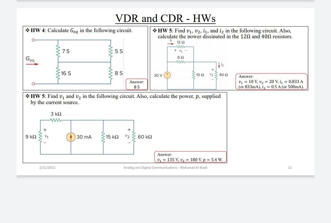
Transcribed Image Text:VDR and CDR - HWs
* HW 4: Calculate Geg in the following circuit.
* HW 5: Find v1, v2, i1, and i2 in the following circuit. Also,
calculate the power dissipated in the 120 and 400 resistors.
- 12 0
ww
+ y -
75
5 S
Geg
www
16 S
8 S
10 2
v2 E 40 2
30 V
Answer:
v1 = 10 V, v2 = 20 V, i, = 0.833 A
(or 833mA), iz = 0.5 A (or 500mA)
Answer:
8S
* HW 5: Find v, and v2 in the following circuit. Also, calculate the power, p, supplied
by the current source.
3 k2
9 k2
V1
30 mA
15 k2
V2
60 k2
Answer:
v, = 135 V, v, = 180 V. p = 5.4 W.
2/21/2021
Analog and Digital Communications - Mohanad Al-Ibadi
12
ww ww
Expert Solution
This question has been solved!
Explore an expertly crafted, step-by-step solution for a thorough understanding of key concepts.

This is a popular solution!

Trending now
This is a popular solution!

Step by step
Solved in 3 steps with 3 images

Knowledge Booster


Learn more about
Need a deep-dive on the concept behind this application? Look no further. Learn more about this topic, electrical-engineering and related others by exploring similar questions and additional content below.Recommended textbooks for you
Introductory Circuit Analysis (13th Edition)
Electrical Engineering
ISBN:
9780133923605
Author:
Robert L. Boylestad
Publisher:
PEARSON

Delmar's Standard Textbook Of Electricity
Electrical Engineering
ISBN:
9781337900348
Author:
Stephen L. Herman
Publisher:
Cengage Learning

Programmable Logic Controllers
Electrical Engineering
ISBN:
9780073373843
Author:
Frank D. Petruzella
Publisher:
McGraw-Hill Education
Introductory Circuit Analysis (13th Edition)
Electrical Engineering
ISBN:
9780133923605
Author:
Robert L. Boylestad
Publisher:
PEARSON
Delmar's Standard Textbook Of Electricity
Electrical Engineering
ISBN:
9781337900348
Author:
Stephen L. Herman
Publisher:
Cengage Learning
Programmable Logic Controllers
Electrical Engineering
ISBN:
9780073373843
Author:
Frank D. Petruzella
Publisher:
McGraw-Hill Education

Fundamentals of Electric Circuits
Electrical Engineering
ISBN:
9780078028229
Author:
Charles K Alexander, Matthew Sadiku
Publisher:
McGraw-Hill Education

Electric Circuits. (11th Edition)
Electrical Engineering
ISBN:
9780134746968
Author:
James W. Nilsson, Susan Riedel
Publisher:
PEARSON

Engineering Electromagnetics
Electrical Engineering
ISBN:
9780078028151
Author:
Hayt, William H. (william Hart), Jr, BUCK, John A.
Publisher:
Mcgraw-hill Education,