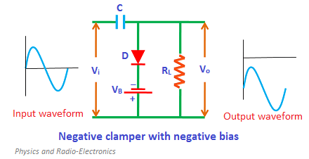
Vi RL Vo VB. nput waveform Output wavefor Negative clamper with negative bias ww-


Q: Figure 2-18 shows a one-line diagram of a small 480-V industrial distribution system. The power syst...
A: WYE connection: If we connect together one side terminals of the poly-phase winding, a WYE connectio...
Q: A real continuous-time LTI system is given by the block diagram below. E(s) G(s) R(s) Y(s) The input...
A:
Q: What is the name of the gadget that can determine the distance between a cable's damage and where it...
A: Name of the gadget which is used for finding the cable damage and its location is "Cable Fault Locat...
Q: Given a non inverting op – amp below, what should be the operating frequency to have a high frequenc...
A: The circuit is given as We know that the frequency response of opamp is like a low pass filter.
Q: 1. For the circuit shown, find the current I through the 6 Q resistor using Thevenin's Theorem R-62 ...
A:
Q: For the system shown, determine the peak time, Tp.
A:
Q: Find the phasor representations of the following sinusoidal voltages and currents. a. v(t) = 10 cos(...
A: The given voltage and current expression should be converted as similar to the general expression of...
Q: A three-phase load is balanced if all the three phases have the same impedance impedance and power f...
A:
Q: Explain the block diagram of a induction furnace unit
A: There are various electrical machines and devices used in day to day life. Efficiency and regulation...
Q: E. Şekildeki devre için çevre akımları yöntemini kullanarak denklemleri yazınız. ww. 20 Ohm ww. 4 Oh...
A:
Q: 2. Reduce the following block diagrams to canonical form and determine the transfer function C/R. Ex...
A: Given block diagram can be solved using Mason's gain formula or graph theory.
Q: Analyze AC network using Mesh-Current Analysis. Find the branch currents indicated in the following ...
A: In this question, We need to determine the branch currents indicated in the following networks. An...
Q: a I1 20 212 V.079 I3 ell jia b' 10 420°A -j207 22 V,071 Is 12 e
A: To find all currents through kirchoff's law
Q: 34. Determine the average ac resistance for the diode of Fig. 15 for the region between 0.6 V and 0....
A:
Q: Find the mean current and the RMS current from t=0.0s to t=4.0s if i= (1.0t+1.0/t) Round to the near...
A:
Q: Audio amp: 35 dB gain (a) What is the total power gain of the receiver from antenna to speaker? (b) ...
A: aTotal power gain of the receiver from antenna to speaker calculation:PG=GRF-Lmix+GIF-Ldet+GAFSubsti...
Q: Determine the output C for the system represented in figure below:
A: The response can be obtained by calculating the output response for individual input and the overall...
Q: Using re model, compute for the AC characteristic of below circuit. (Zo) 15 V 10 ΚΩ 45 k2 21 k2 10 μ...
A: We need to find out output impedance for given circuit
Q: Using re model, compute for the AC characteristic of below circuit. (Av) 15 V 10 k2 45 k2 21 k2 10 μ...
A:
Q: 3.52 Find the power dissipated in the 18 resistor in the PSPICE circuit in Fig. P3.52. MULTISIM Figu...
A: We need to find out power dissipated by 18 ohm resistor
Q: 3) For the circuit in Figure 6.6, use superposition to determine V1 and V2. 2.7kQ + V2 - 1k2 3.3kn 5...
A: Superposition theorem: It tells that if there is a linear bilateral network containing more than one...
Q: A capacitor of 1µF is connected to a 50 Hz supply. The capacitive reactance is ___. Kindly provide a...
A: Simply use the formula for capacitive reactance (Xc)
Q: 220N + 330N 470 L R 91Ω ET 15 V Ern, RTh
A: Thevenin's Resistance It is the open circuit resistance across the load when all the independent s...
Q: In all electrical machines, the core is made of iron always in spite of its cost, weight, eddy curre...
A: In all electric machine, we basically want core to be made of such material that it has high permeab...
Q: Calculate the frequency for a given periodic time of 50 us O 20 kHz O 0.2 kHz O 200 kHz O2 kHz
A:
Q: Find the pull exerted on the plunger of an electromagnet when the total flux is 381 uWb. The diamete...
A:
Q: Solve the Eth and Rth using Thevenin's Theorem
A:
Q: The diode starts to conduct when the voltage across it is 0.6 V. Vin is a variable DC voltage source...
A: To find the input voltage at which diode starts to conduct
Q: The inverse Laplace transform of the following function is: 6. F(s) = (s+5)4 O a. He-5tu(t-5) Ob. 3e...
A:
Q: What is Inductance and inductor? 2. What is Capacitance and capacitor? 3. Difference between inducto...
A: Inductor resists changes in current Capacitor resists changes in voltage Inductor stores energy in t...
Q: A balanced delta connected load draws 10 A of line current and 3 kW at 220 V. reactance of each phas...
A:
Q: Assuming ideal diodes, draw the output waveform of the circuit to the given input waveform.
A:
Q: 10. A 110-Volt AC line feeds two circuits in parallel. The currents are (2.2 - j6.5)A and (1.8 – j3....
A: Since you have asked for question 10 . So we are providing solution for question 10 . This question ...
Q: Using re model, compute for the AC characteristic of below circuit. a. Zi b. Zo c. Av d. Ai
A: The required parameters of collector DC feedback configuration of CE amplifier can be calculated by ...
Q: 2. Sketch the following convolutions: a(t) = rect b(t) = ("C. 9, 0く) 0 <t <1 other c(t) = 8(t – 1) (...
A:
Q: For the underdamped second-order system with specifications %OS = 12% and Ts = 0.6 s, find the magni...
A: Given that: %overshoot=12% Ts=0.6s and underdamped second-order system we need to find the magnitude...
Q: iv. When the half power point bandwidth is 10 MHz and the center frequency is 5MHZ, the quality fact...
A:
Q: Q2. Refer to the circuit as shown in Figure Q2 and assume that the circuit has reached a steady-stat...
A: We are authorized to answer three subparts at a time, since you have not mentioned which part you ar...
Q: QUESTION #5. Ob. Assuming ideal diodes, select from the choices shown the output waveform of the cir...
A: We need to select correct option for given circuit
Q: capacitor to alternating current of frequency 50Hz is 10ohms. If the frequency is increased to 100Hz...
A: Reactance and frequency are inversely proportional for capacitor
Q: The admittance of a 2H inductor in the S-domain is: a. 2/s ohm O b. 1/(2s) ohm O c. s/2 ohm O d. Non...
A: The solution is given below
Q: 10.3 Starting from the expression of fr for a MOSFET, fr 2æ(C,+C,a) and making the approximation tha...
A: It is given that: fT=gm2πCgs+Cgd
Q: I1 0.5Vx j20 1220° v Vx. 12 Ix I2 420°A 1Ix -j12 I3 ell
A:
Q: An induction motor OF 30 HP, 220 V, 450% of the rated current with the rated voltage and delivers du...
A: During starting of induction motor we have following formula: TstTf=IscIf2sf1.3TfTf=4.5IfIf2sfsf=1.3...
Q: For the given circuit for a 13.04 Vpeak sinusoidal input Vin, what is the value of Vout (in V) when ...
A: The diode will conduct only during the positive half of the input cycle. so replace the diode with i...
Q: Are the signals periodic or not? If it's periodic, what's the period? Show it by calculating. a)...
A: The solution is given below
Q: Find the branch currents using Kirchhoff's Laws
A: In these circuit, Find the branch currents using Kirchhoff's Laws i.e KCL and KVL. We are represent...
Q: Find the sum of the poles of the system represented in state space below. 8 -4 1 -4" -3 2 0 x + -3 u...
A:
Q: A three-phase, four-pole induction motor, connected at ∆, 220V, 60Hz, presents rotational losses of ...
A:
Q: C(s) for the signal flow graph shown below R(s) eulate the transfer function a2 az a4 C(s) C(s) а) R...
A:
Create and illustrate one solved problem using the image below

Step by step
Solved in 2 steps with 2 images


- plz solve this signal and system subject ...The given Oscillator,a) Draw the small sign model,b) Determine the oscillator frequency and oscillation condition.VDD: 8V Rp = 7006 Ω,Other Remaining Resistor, Inductance and Capacitor shipping you specify.ma=Acmax-Acmin/Acmax+Acmin for the modulated signal (AM) ,ma = 0.25;Calculate Acmax, Acmin and efficiency value.
- Construct MOD 12 asynchronous counter. What will be the output frequency, if the input frequency is 1 MHz. If the counter is at state 6, what will be the count after 60 pulses.a) Sketch the input-output characteristics curve of the circuit. b) Sketch the output waveform.A2 Briefly, but informatively, describe importance laser ablation in combination with ICP-MS in solid sample. Cite Reference/s
- A WBFM modulator comprises the following blocks (in this order). (i) a NBFM with carrier output f1=1Mhz and carrier deviation 4.5 khz); (ii) a frequency multiplier n1 =5; an up converter using a 25 Mhz oscillator and (iv) a frequency multiplier n2=3. Determine the output carrier and deviation frequencies of this WBFM modulator.design monostable multivibrator,astable mutivibbrator, bistable multivibrator using multisim by using 555 timer IC,tiemperiod. and also by using transistor?Given Vi = 20V peak-to-peak, draw the output waveform for the said clamper circuit below:
- Explain wein bridge oscillator in detail. give its advantages and disadvantages in detailMultiple Choice directions: Circle the letter of the answers that best answer the question. 13. When using microwave tubes as amplifiers, what is used as bandpass filters? a. Transistors b. Oscillator c. All of the above d. Power tubes 14. The microstrip lines used to achieve maximum power transfer are intended for a. Signal coupling b. Decoupling to prevent feedback c. Low-noise amplification d. Impedance matching and tuning 15. A diode that when reverse biased will momentarily and will abruptly turn off. a. Varactor diode b. IMPATT c. Step recovery diodes d. PIN diodes 16. A microwave transmission line used to minimize noise and crosstalks. a. Stripline b. Hard line cable c. Waveguide d. Microstrip 17. The major difference between a low frequency transistors and microwave types is/are. a. B & C b. Packaging c. Material d. Internal geometry 18. Which of the following band belongs to the millimeter waves a. C b. Ku c. U d. L 19. Overcrowding in the frequency spectrum is prevalent…Find the Value of output voltage Vo(t), in volts (V), after two seconds given the input signal below and the value of R = 1Kohm, C = 0.1uF and the period (T) of input signal is 1 second.