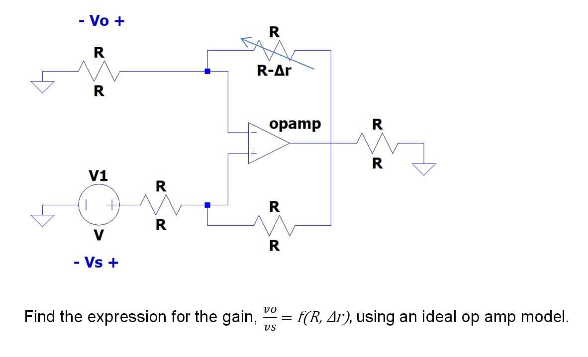
- Vo + R R-Ar R opamp R R V1 R R V R - Vs + vo Find the expression for the gain, = f(R, Ar), using an ideal op amp model. vs R. R.


Q: a. Determine r.. b. Find A, = Vo/Vj- c. Calculate Z;. d. Determine fLofLo and fL- e. Determine the l...
A: As per company guidelines we can solve only first three sub parts kindly post another parts separate...
Q: Question 2. Consider the following period signal r(t) =t-n. 0stS 27 (t) 27 (a) ) By direct integrati...
A: We need to find Fourier series coefficient for given waveform
Q: Find Vour(t) given Vin(t) in the op amp circuit that follows. out L R ell in Vout?)
A:
Q: Given a balanced 3 wire, three phase system serving an unbalanced wye connected load. Determine the...
A:
Q: A voltage of 200 V is applied to a series circuit consisting on a resistor, an inductor and a capaci...
A: The solution is given below
Q: and Voutz in terms of V, V,, and R. 5.6. For the following circuit, express Iout,
A:
Q: You should find that this circuit emits a much louder tone than the one from the previous lab, since...
A: The buzzer will be ON when the switch will be in a close position. Now the circuit will be in a clos...
Q: The input to a 11-kv, 30, y-connected SYnchronous mator is 60a The effective vesistance Ond 6ynchran...
A: In this question, Star connected synchronous motor is given. Find the power supplied by the motor ...
Q: QUESTION 6 • For the given circuit, sketch Vo and determine its equivalent the DC voltage. Idcal 22 ...
A:
Q: a. Determine r.. b. Find A, = Vo/Vi- c. Calculate Z;. d. Determine fLsfLe e. Determine the low cutof...
A: Brief description : In the above given question they have mentioned a common collector amplifier cir...
Q: Please show a complete solution to the problem 7. A 100-hp, three-phase, wye-connected, 50-Hz, 450-...
A:
Q: In repulsion type moving iron instrument, fixed vane is attached to the
A: Repulsion type moving iron: This type of instrument works on both AC and DC. When a current is flowi...
Q: With respect to 8051 microcontroller, the programming address of TFO and IEO of a timer control spec...
A: Given that for 8051 microcontroller ,the programming adress of TF0 and IE0 needs to be identified. ...
Q: A sinusoidal 50 Hz voltage of 200 V (rms) supplies the following three circuits which are in paralle...
A: Considering the circuit diagram.
Q: When investigating the charging/discharging mode of the RC Circuit, do you think the internal resist...
A: Solution - When capacitors and resistors are interconnected, the resistor prevents the transfer of c...
Q: a) Design the 4-bit R-2R ladder network D/A converter shown in Figure 2(a) such that Vo = -5 Vref at...
A:
Q: For the amplifier below calculate the voltage gain (Av) if R1 = 3.3 kN and Rf = 5.6 kN? Rf +Vc R1 Vi...
A:
Q: The value of transformation ratio (K) for the step up transformer is a) equal to 0 b) less than 1 c)...
A: Answer: greater than 1 Explanation: a) It is not a valid option. If k=0 then the secondary turns ...
Q: A 50-Hz, 250-V single-phase power line has the following loads placed across it in parallel : 4 kW a...
A: The solution is given below
Q: . Compute the Fourier transform of each of the following signals (a) x[n] : E u[-n- 1]
A: As per our guidelines we are supposed to answer only first question. Kindly repost the other questio...
Q: 4. A two-port network is shown below. 10 10 Determine the hybrid-parameter (h-parameter) representat...
A:
Q: c) An ADC is used to convert an analogue signal of 12 V to digital signal. Show step by step how suc...
A: A successive-approximation ADC is a type of analog-to-digital converter that converts a continuous a...
Q: 20 V Ip 12 V Si AGe Şi GaAs 4.7 k2 2.2 k2 6 4 V (a) (b)
A:
Q: percent
A:
Q: Refer to the given circuit below. Determine the equivalent resistance across terminals b and d if R1...
A: While calculating the equivalent resistance of the circuit, The resistance which is connected at ope...
Q: I, = 2 A Z 0° %3D IR YT 20 XL 50 E ll +
A: We need to find out admittance and current and power factor for given circuit
Q: 10.8 오
A: Given, We have a network with resistances. We have to find the equivalent resistance across node b a...
Q: 1. Draw Bode Plot for given transfer function by means of HAND. 10 G(s) s(s + 1)
A: Bode plot: This is the graph between the magnitude of the transfer function and frequency w.
Q: B- For the potentiometer in the below network: 80 0 Pot. I K Va 1-What are the voltages Vab and Vbc ...
A: We need to find voltage and power with load and without load condition
Q: The deep wel pump motor is 50hp, 3-phase, 4- poles, 230volts, 60hz induction mator operating at 0.90...
A:
Q: 2. Find the GMR of a conductor in terms of the radius r of an individual strand for (a) Three equal ...
A: In this question we need to find a GMR of the given conductor.
Q: Determine the value of vi if Vs=0V and Is=3mA Vs 6k2
A: SOLUTION- If Vs = 0 V and Is = 3mA 6 kohm & 3 kohm are in parallel , = 6×36+3 = 2 kohm t...
Q: Calculate the total charge present within the region -8 < p <7, -1.6n < p < 1.2t, -5 < z < 10, given...
A:
Q: Given: flux per pole = 1,900,000 maxwells; pole pitch = 6.25; gross length of armature core = 10 inc...
A:
Q: 8. Determine the truth table of the digital eircuit shown in the figure below and explain its operat...
A: We need to find out logic Operation of given circuit
Q: 2. Show how the output conductance of a transistor affects the voltage transfer characteristics (but...
A: Transfer characteristic of a cross coupled inverter represent the the relation between the input and...
Q: 21. For a lossless transmission line, determine the value of the input impedance given: ZL = 25 +j72...
A: Dear,as per company guidelines we can answer only one question at a time, kindly post other question...
Q: Question # 3 For given circuit, Vs = 25 Volts, R1 = 22002, R2 = 25,0002, R3 = 10002, R4 = 50,0002, R...
A: Current and voltage division is an important techniques to find the current in parallel branches and...
Q: VR (V) a R Vc Vo (A) I (V
A: We need to analyse the series RC circuit
Q: Refer to the given circuit below. Determine the equivalent resistance across terminals a and b if R...
A:
Q: Given a one line diagram below. Determine the Apparent power and power factor of Alternator A. A 4,5...
A:
Q: In the figure below, what value of RS will provide an LED current of 20 mA?
A: Replace the red LED with its voltage drop and apply ohm's law to find the value of the resistor to a...
Q: Give three common electrical devices at home. For each device, give three important safety precautio...
A: Nowadays,with evolution of power electronic and Integrated circuits, The use of electrical devices i...
Q: Find the incremental change in iA for a 2% increase in the value of R.
A: Given: The circuit below contains a nonlinear element N whose v-i relationship is given by: iA=c2vA2...
Q: Q1) A- What is the total cost of using the following at 6C per kilowatthour? a) 1200 W air condition...
A: As per the guidelines of Bartley we supposed to answer first three subpart only.
Q: An ammeter has a PMMC instrument with a coil resistance of Rm- 99 Q and FSD current of 0.1 mA, shunt...
A: For PMMC ammeter the current through coil resistance is given and the value of both coil resistance ...
Q: Comment briefly on the relationship between input and output power at varying excitation levels and ...
A: Answer - It is an very important topic that we should know about the synchronous machine infinite bu...
Q: What is the importance of electrical supplies, materials, and tools in residential houses and agricu...
A: Given that we need to outline the importance of electrical supplies and tools in residential and agr...
Q: 2. For the Fourier series given by 2mn cos 10 n=1 120nT y(t) = 4 + NTT t+ 4 NT sin 4 30 where t is t...
A:
Q: 1. Consider a periodic discrete-time square signal x[n] given by n -N, 0 N where the x[n] is equal t...
A:
Show your complete solution.

Step by step
Solved in 3 steps with 3 images


- Is it possible to get a gain less than unity using a non-inverting amplifier configuration? If yes, sketch a circuit.''please solve it in computer font, not on paper''Please show that gain = -(1-n)/(1+nA) , n = R1/(R1+R2) and compare to gain of ideal op amp. Calculate the input and output impedances, and lastly whats the point of the resistor R1//R2 on the non-inverting input? What would be the best value for this resistor? (pretending it wasn't given that the value is R1/R2).Consider the active circuit with the schematic:a. Assuming it's an ideal op amp, derive the circuit’s transfer function as a function of frequency, H(jw). Make sure it in canonical form.b. We want a DC gain of 40dB. If the op amp has value of Rin = 10MΩ and Rout = 50Ω, choose appropriate values for R1 and R2. Explain why your selected values of R1 and R2 allow you to ignore Rin and Rout for the remainder of the problem. c. If L = 1H, sketch the straight-line approximation of the Bode plot for the circuit’s gain assuming the op amp can still be considered as ideal.d. The op amp you select turns out to be non-ideal, and it has a real pole at wC = 1krad/s. Write the updated transfer function for your circuit (using your values of R1, R2, and L = 1H). Make it in the canonical form.e. Sketch the straight-line approximation of the Bode plot for the circuit with your updated transfer function from D.
- Consider the active circuit with the schematic:a. Assuming it's an ideal op amp, derive the circuit’s transfer function as a function of frequency, H(jw). Make sure it in canonical form.b. We want a DC gain of 40dB. If the op amp has value of Rin = 10MΩ and Rout = 50Ω, choose appropriate values for R1 and R2. Explain why your selected values of R1 and R2 allow you to ignore Rin and Rout for the remainder of the problem.An op amp has a gain of 100 dB at dc and a unity-gain frequency of 5 MHz. What is fB? Write the transfer function for the gain of the op amp.Given circuit, assume op-amp is ideal. What is the input resistance of the circuit, RIN? What are the currents in the inputs of op-amp? i-=? i+=? What is the output resistance of the circuit, ROUT=? Find voltage VA and VB? What is the nodal equation (KCL) at node VB? Solve for VOUT=?
- a) Design a non-inverting amplifier using an ideal op amp that has a gain 7.5.b) If you wish to amplify signals between -2V and 1.2V using the circuit you designed in part (a) what arethe smallest power supply voltages you can use?c) Draw your final circuit diagram.d) Assume that the voltage signal source is vs = −1V and the feedback resistor Rf is replaced with avariable resistor. Specify the range of Rf (in kΩ ) which will cause the op amp to saturate?Consider the active circuit:a. Assuming it's an ideal op amp, derive the circuit’s transfer function as a function of frequency, H(jw) in canonical form.b. We want a DC gain of 40dB. If the op amp has value of Rin = 10MΩ and Rout = 50Ω, choose appropriate values for R1 and R2. Explain why your selected values of R1 and R2 allow you to ignore Rin and Rout for the remainder of the problem.For the op-amp circuit shown below, find the value of vO, where R1 = 19 Ω, R2 = 14 Ω, R3 = 18 Ω, R4 = 14 Ω, Rf = 11 Ω, VS1 = 15 V, and VS2 = 3 V.
- Using the components listed below, design an amplifier having a voltage gain of −10 ± 20 percent. The input impedance is required to be as large as possible (ideally, an open circuit). Remember to use practical resistance values. Cascade a non-inverting stage with an inverting stage.1) Standard 5%-tolerance resistors.2) Standard 1%-tolerance resistors. (Don’t use these if a 5%-tolerance resistor will do, because 1%-tolerance resistors are more expensive.)3) Ideal op-amps.4) Adjustable resistors (trimmers) having maximum values ranging from 100 Ω to 1 MΩ in a 1–2–5 sequence (i.e., 100Ω, 200Ω, 500Ω, 1 kΩ, etc.). Don’t use trimmers if fixed resistors will suffice.For the circuit below, use superposition to find vO in terms of the input voltages v1 and v2. Assume an ideal op amp. v1= 8sin(2??x60t)- 0.1sin(2??x5000t) volts and v2 =8sin(2??x60t) +0.1sin(2??x5000t) voltsThe open-loop gain A of real (nonideal) op-amps isvery large at low frequencies but decreases markedlyas frequency increases. As a result, the closed-loopgain of op-amp circuits can be strongly dependent on frequency. Determine the relationship between a finiteand frequency-dependent open-loop gain AV(OL)(ω)and the closed-loop gain AV(CL)(ω) of an invertingamplifier as a function of frequency. Plot AV(CL)versus ω. Notice that −RF/RS is the low-frequencyclosed-loop gain.