Voltages de and when operating at resistive load and inc ctive rms Repeat step (3) above, at (a =72°). Comment on your results.
Voltages de and when operating at resistive load and inc ctive rms Repeat step (3) above, at (a =72°). Comment on your results.

Introductory Circuit Analysis (13th Edition)
13th Edition
ISBN:9780133923605
Author:Robert L. Boylestad
Publisher:Robert L. Boylestad
Chapter1: Introduction
Section: Chapter Questions
Problem 1P: Visit your local library (at school or home) and describe the extent to which it provides literature...

Related questions
Question
Transcribed Image Text:Experiment-3
Power Electronics Lab.
(Practical)
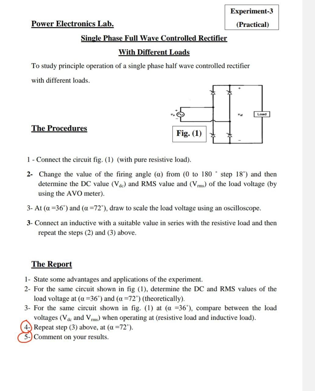
Single Phase Full Wave Controlled Rectifier
With Different Loads
To study principle operation of a single phase half wave controlled rectifier
with different loads.
Load
The Procedures
Fig. (1)
1 - Connect the circuit fig. (1) (with pure resistive load).
2- Change the value of the firing angle (a) from (0 to 180 ° step 18°) and then
determine the DC value (Vde) and RMS value and (Vms) of the load voltage (by
using the AVO meter).
3- At (a =36°) and (a =72°), draw to scale the load voltage using an oscilloscope.
3- Connect an inductive with a suitable value in series with the resistive load and then
repeat the steps (2) and (3) above.
The Report
1- State some advantages and applications of the experiment.
2- For the same circuit shown in fig (1), determine the DC and RMS values of the
load voltage at (a =36') and (a =72") (theoretically).
3- For the same circuit shown in fig. (1) at (a =36°), compare between the load
voltages (Vdc and Vms) when operating at (resistive load and inductive load).
4 Repeat step (3) above, at (a =72°).
5-) Comment on your results.
Expert Solution
This question has been solved!
Explore an expertly crafted, step-by-step solution for a thorough understanding of key concepts.

Step by step
Solved in 5 steps with 5 images

Knowledge Booster


Learn more about
Need a deep-dive on the concept behind this application? Look no further. Learn more about this topic, electrical-engineering and related others by exploring similar questions and additional content below.Recommended textbooks for you
Introductory Circuit Analysis (13th Edition)
Electrical Engineering
ISBN:
9780133923605
Author:
Robert L. Boylestad
Publisher:
PEARSON

Delmar's Standard Textbook Of Electricity
Electrical Engineering
ISBN:
9781337900348
Author:
Stephen L. Herman
Publisher:
Cengage Learning

Programmable Logic Controllers
Electrical Engineering
ISBN:
9780073373843
Author:
Frank D. Petruzella
Publisher:
McGraw-Hill Education
Introductory Circuit Analysis (13th Edition)
Electrical Engineering
ISBN:
9780133923605
Author:
Robert L. Boylestad
Publisher:
PEARSON
Delmar's Standard Textbook Of Electricity
Electrical Engineering
ISBN:
9781337900348
Author:
Stephen L. Herman
Publisher:
Cengage Learning
Programmable Logic Controllers
Electrical Engineering
ISBN:
9780073373843
Author:
Frank D. Petruzella
Publisher:
McGraw-Hill Education

Fundamentals of Electric Circuits
Electrical Engineering
ISBN:
9780078028229
Author:
Charles K Alexander, Matthew Sadiku
Publisher:
McGraw-Hill Education

Electric Circuits. (11th Edition)
Electrical Engineering
ISBN:
9780134746968
Author:
James W. Nilsson, Susan Riedel
Publisher:
PEARSON

Engineering Electromagnetics
Electrical Engineering
ISBN:
9780078028151
Author:
Hayt, William H. (william Hart), Jr, BUCK, John A.
Publisher:
Mcgraw-hill Education,