What is the efficiency of the generator at these conditions?

Power System Analysis and Design (MindTap Course List)
6th Edition
ISBN:9781305632134
Author:J. Duncan Glover, Thomas Overbye, Mulukutla S. Sarma
Publisher:J. Duncan Glover, Thomas Overbye, Mulukutla S. Sarma
Chapter12: Power System Controls
Section: Chapter Questions
Problem 12.11P

Related questions

Question
SYNCHRONOUS GENERATOR
answer #2
Transcribed Image Text:Your answer
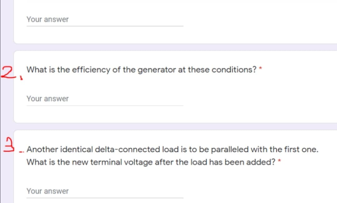
2. What is the efficiency of the generator at these conditions? *
Your answer
3. Another identical delta-connected load is to be paralleled with the first one.
What is the new terminal voltage after the load has been added? *
Your answer
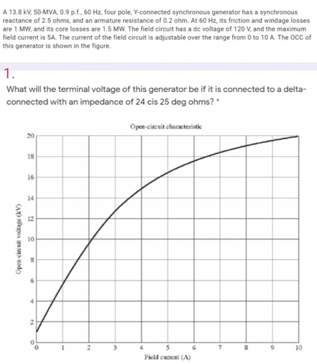
Transcribed Image Text:A 13.8 kV, 50-MVA, 0.9 p.f., 60 Hz, four pole, Y-connected synchronous generator has a synchronous
reactance of 2.5 ohms, and an armature resistance of 0.2 ohm. At 60 Hz, its friction and windage losses
are 1 MW, and its core losses are 1.5 MW. The field circuit has a dc voltage of 120 V, and the maximum
field current is 5A. The current of the field circuit is adjustable over the range from 0 to 10 A. The OCC of
this generator is shown in the figure.
1.
What will the terminal voltage of this generator be if it is connected to a delta-
connected with an impedance of 24 cis 25 deg ohms? *
Open-circuit characteristic
20
18
16
14
12
10
3.
4
5
6.
10
Field cument (A)
Open-circuit voltage (kV)
00
Expert Solution
This question has been solved!
Explore an expertly crafted, step-by-step solution for a thorough understanding of key concepts.

Step by step
Solved in 4 steps

Knowledge Booster


Learn more about
Need a deep-dive on the concept behind this application? Look no further. Learn more about this topic, electrical-engineering and related others by exploring similar questions and additional content below.Recommended textbooks for you
Power System Analysis and Design (MindTap Course …
Electrical Engineering
ISBN:
9781305632134
Author:
J. Duncan Glover, Thomas Overbye, Mulukutla S. Sarma
Publisher:
Cengage Learning
Power System Analysis and Design (MindTap Course …
Electrical Engineering
ISBN:
9781305632134
Author:
J. Duncan Glover, Thomas Overbye, Mulukutla S. Sarma
Publisher:
Cengage Learning