What is the value of the quality factor in the following circuit during resonant frequency? 100 A 50 mH 12 cos ul V :5 µF 1 100 None of the answers 10 O O
What is the value of the quality factor in the following circuit during resonant frequency? 100 A 50 mH 12 cos ul V :5 µF 1 100 None of the answers 10 O O

Delmar's Standard Textbook Of Electricity
7th Edition
ISBN:9781337900348
Author:Stephen L. Herman
Publisher:Stephen L. Herman
Chapter24: Resistive-inductive-capacitive Parallel Circuits
Section: Chapter Questions
Problem 4RQ: A tank circuit contains a capacitor and an inductor that produce 30 of reactance at the resonant...

Related questions
Question
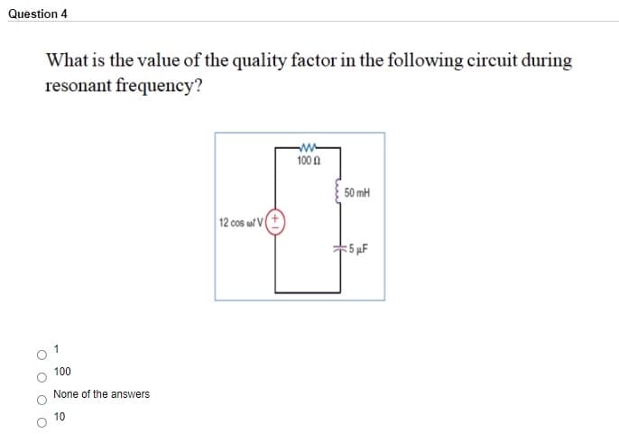
Transcribed Image Text:Question 4
What is the value of the quality factor in the following circuit during
resonant frequency?
100 0
50 mH
12 cos wl VI
5 µF
1
100
None of the answers
10
Expert Solution
This question has been solved!
Explore an expertly crafted, step-by-step solution for a thorough understanding of key concepts.

Step by step
Solved in 2 steps

Knowledge Booster


Learn more about
Need a deep-dive on the concept behind this application? Look no further. Learn more about this topic, electrical-engineering and related others by exploring similar questions and additional content below.Recommended textbooks for you
Delmar's Standard Textbook Of Electricity
Electrical Engineering
ISBN:
9781337900348
Author:
Stephen L. Herman
Publisher:
Cengage Learning
Delmar's Standard Textbook Of Electricity
Electrical Engineering
ISBN:
9781337900348
Author:
Stephen L. Herman
Publisher:
Cengage Learning