Why forces are generated for parts of the loop (actually rectangle in Fig 20-37) and not for other parts of the loop. Refer back to Fig 20-11 and the Force equation with sin theta (max force when theta is 90 degrees or perpendicular to magnetic field lines.) your experience applying the Right-Hand Rule to explain up and down forces acting together to generate clockwise motion of the armature
Why forces are generated for parts of the loop (actually rectangle in Fig 20-37) and not for other parts of the loop. Refer back to Fig 20-11 and the Force equation with sin theta (max force when theta is 90 degrees or perpendicular to magnetic field lines.) your experience applying the Right-Hand Rule to explain up and down forces acting together to generate clockwise motion of the armature

College Physics
11th Edition
ISBN:9781305952300
Author:Raymond A. Serway, Chris Vuille
Publisher:Raymond A. Serway, Chris Vuille
Chapter19: Magnetism
Section19.5: Magnetic Force On A Current -Carrying Conductor
Problem 19.3QQ: As a charged particle moves freely in a circular path in the presence of a constant magnetic field...

Related questions

Question
Please type your Solutions so that they are easy to read I have bad eyesight
Transcribed Image Text:N
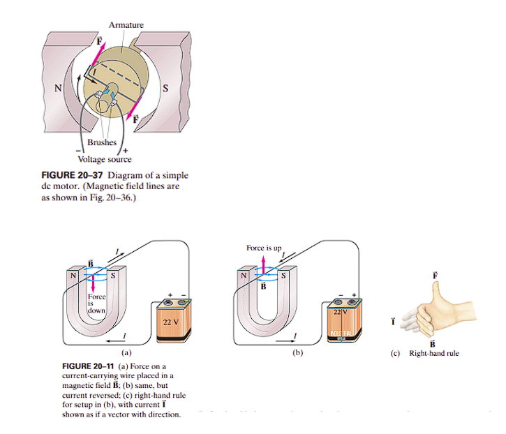
Armature
Force
IS
down
F
S
Brushes
Voltage source
FIGURE 20-37 Diagram of a simple
de motor. (Magnetic field lines are
as shown in Fig. 20-36.)
22 V
(a)
FIGURE 20-11 (a) Force on a
current-carrying wire placed in a
magnetic field B; (b) same, but
current reversed; (c) right-hand rule
for setup in (b), with current I
shown as if a vector with direction.
Force is up
(b)
22 V
INDUSTRIAL
B
(c) Right-hand rule
Transcribed Image Text:Why forces are generated for parts of the loop (actually rectangle in Fig 20-37) and not for other
parts of the loop. Refer back to Fig 20-11 and the Force equation with sin theta (max force
when theta is 90 degrees or perpendicular to magnetic field lines.)
your experience applying the Right-Hand Rule to explain up and down forces acting together to
generate clockwise motion of the armature
Expert Solution
This question has been solved!
Explore an expertly crafted, step-by-step solution for a thorough understanding of key concepts.

Step by step
Solved in 4 steps with 3 images

Knowledge Booster


Learn more about
Need a deep-dive on the concept behind this application? Look no further. Learn more about this topic, physics and related others by exploring similar questions and additional content below.Recommended textbooks for you
College Physics
Physics
ISBN:
9781305952300
Author:
Raymond A. Serway, Chris Vuille
Publisher:
Cengage Learning

College Physics
Physics
ISBN:
9781285737027
Author:
Raymond A. Serway, Chris Vuille
Publisher:
Cengage Learning

Physics for Scientists and Engineers: Foundations…
Physics
ISBN:
9781133939146
Author:
Katz, Debora M.
Publisher:
Cengage Learning
College Physics
Physics
ISBN:
9781305952300
Author:
Raymond A. Serway, Chris Vuille
Publisher:
Cengage Learning
College Physics
Physics
ISBN:
9781285737027
Author:
Raymond A. Serway, Chris Vuille
Publisher:
Cengage Learning
Physics for Scientists and Engineers: Foundations…
Physics
ISBN:
9781133939146
Author:
Katz, Debora M.
Publisher:
Cengage Learning

Principles of Physics: A Calculus-Based Text
Physics
ISBN:
9781133104261
Author:
Raymond A. Serway, John W. Jewett
Publisher:
Cengage Learning


Glencoe Physics: Principles and Problems, Student…
Physics
ISBN:
9780078807213
Author:
Paul W. Zitzewitz
Publisher:
Glencoe/McGraw-Hill