You are hired as a technical consultant to model, design and analyze an efficient DC-DC buck converter for a solar PV battery charger as shown in the below figure. PV DC-DC Battery system Converter MPPT Charge controller algorithm Given the following specifications for the design and analysis of a DC-DC Buck Converter: An input voltage of 15V < Vin < 20V and an output of Vout = 10V over a load range of Sw < Pout < 200W. Switching frequency is fcw = 500kHz. a) Design the inductor (L) and capacitor (C). The current ripple AiL should be below 5% oft average inductor current IL at the maximum load. The steady state ripple AVout is below ( % of the steady-state value of the output voltage. For the designed L, find the value
You are hired as a technical consultant to model, design and analyze an efficient DC-DC buck converter for a solar PV battery charger as shown in the below figure. PV DC-DC Battery system Converter MPPT Charge controller algorithm Given the following specifications for the design and analysis of a DC-DC Buck Converter: An input voltage of 15V < Vin < 20V and an output of Vout = 10V over a load range of Sw < Pout < 200W. Switching frequency is fcw = 500kHz. a) Design the inductor (L) and capacitor (C). The current ripple AiL should be below 5% oft average inductor current IL at the maximum load. The steady state ripple AVout is below ( % of the steady-state value of the output voltage. For the designed L, find the value

Introductory Circuit Analysis (13th Edition)
13th Edition
ISBN:9780133923605
Author:Robert L. Boylestad
Publisher:Robert L. Boylestad
Chapter1: Introduction
Section: Chapter Questions
Problem 1P: Visit your local library (at school or home) and describe the extent to which it provides literature...

Related questions
Question
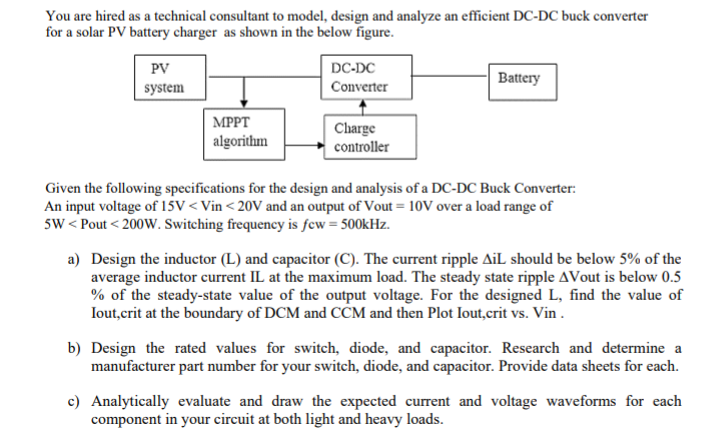
Transcribed Image Text:You are hired as a technical consultant to model, design and analyze an efficient DC-DC buck converter
for a solar PV battery charger as shown in the below figure.
PV
DC-DC
Battery
system
Converter
| MPPT
algorithm
Charge
controller
Given the following specifications for the design and analysis of a DC-DC Buck Converter:
An input voltage of 15V < Vin < 20V and an output of Vout = 10V over a load range of
5w < Pout < 200W. Switching frequency is few = 500kHz.
a) Design the inductor (L) and capacitor (C). The current ripple AiL should be below 5% of the
average inductor current IL at the maximum load. The steady state ripple AVout is below 0.5
% of the steady-state value of the output voltage. For the designed L, find the value of
Iout,crit at the boundary of DCM and CCM and then Plot Iout,crit vs. Vin .
b) Design the rated values for switch, diode, and capacitor. Research and determine a
manufacturer part number for your switch, diode, and capacitor. Provide data sheets for each.
c) Analytically evaluate and draw the expected current and voltage waveforms for each
component in your circuit at both light and heavy loads.
Expert Solution
This question has been solved!
Explore an expertly crafted, step-by-step solution for a thorough understanding of key concepts.

Step by step
Solved in 5 steps with 2 images

Knowledge Booster


Learn more about
Need a deep-dive on the concept behind this application? Look no further. Learn more about this topic, electrical-engineering and related others by exploring similar questions and additional content below.Recommended textbooks for you
Introductory Circuit Analysis (13th Edition)
Electrical Engineering
ISBN:
9780133923605
Author:
Robert L. Boylestad
Publisher:
PEARSON

Delmar's Standard Textbook Of Electricity
Electrical Engineering
ISBN:
9781337900348
Author:
Stephen L. Herman
Publisher:
Cengage Learning

Programmable Logic Controllers
Electrical Engineering
ISBN:
9780073373843
Author:
Frank D. Petruzella
Publisher:
McGraw-Hill Education
Introductory Circuit Analysis (13th Edition)
Electrical Engineering
ISBN:
9780133923605
Author:
Robert L. Boylestad
Publisher:
PEARSON
Delmar's Standard Textbook Of Electricity
Electrical Engineering
ISBN:
9781337900348
Author:
Stephen L. Herman
Publisher:
Cengage Learning
Programmable Logic Controllers
Electrical Engineering
ISBN:
9780073373843
Author:
Frank D. Petruzella
Publisher:
McGraw-Hill Education

Fundamentals of Electric Circuits
Electrical Engineering
ISBN:
9780078028229
Author:
Charles K Alexander, Matthew Sadiku
Publisher:
McGraw-Hill Education

Electric Circuits. (11th Edition)
Electrical Engineering
ISBN:
9780134746968
Author:
James W. Nilsson, Susan Riedel
Publisher:
PEARSON

Engineering Electromagnetics
Electrical Engineering
ISBN:
9780078028151
Author:
Hayt, William H. (william Hart), Jr, BUCK, John A.
Publisher:
Mcgraw-hill Education,