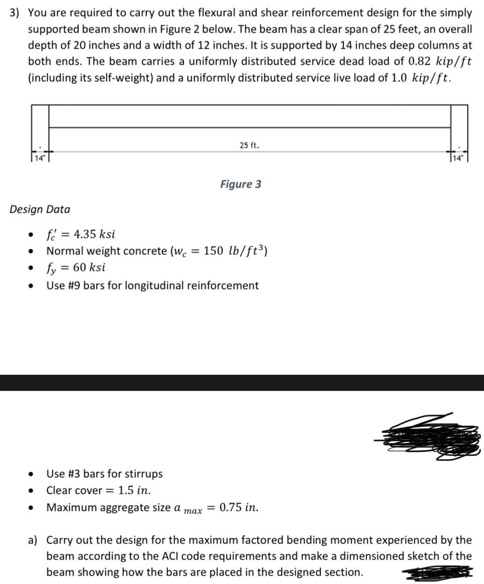
You are required to carry out the flexural and shear reinforcement design for the simply supported beam shown in Figure 2 below. The beam has a clear span of 25 feet, an overall depth of 20 inches and a width of 12 inches. It is supported by 14 inches deep columns at both ends. The beam carries a uniformly distributed service dead load of 0.82 kip/ft (including its self-weight) and a uniformly distributed service live load of 1.0 kip/ft. 25 ft.
You are required to carry out the flexural and shear reinforcement design for the simply supported beam shown in Figure 2 below. The beam has a clear span of 25 feet, an overall depth of 20 inches and a width of 12 inches. It is supported by 14 inches deep columns at both ends. The beam carries a uniformly distributed service dead load of 0.82 kip/ft (including its self-weight) and a uniformly distributed service live load of 1.0 kip/ft. 25 ft.

Chapter2: Loads On Structures
Section: Chapter Questions
Problem 1P

Related questions

Question
Transcribed Image Text:3) You are required to carry out the flexural and shear reinforcement design for the simply
supported beam shown in Figure 2 below. The beam has a clear span of 25 feet, an overall
depth of 20 inches and a width of 12 inches. It is supported by 14 inches deep columns at
both ends. The beam carries a uniformly distributed service dead load of 0.82 kip/ft
(including its self-weight) and a uniformly distributed service live load of 1.0 kip/ft.
Design Data
●
●
●
●
f= = 4.35 ksi
Normal weight concrete (wc =
= 60 ksi
● Use #3 bars for stirrups
● Clear cover = 1.5 in.
fy=
Use #9 bars for longitudinal reinforcement
● Maximum aggregate size a
25 ft.
max
Figure 3
150 lb/ft³)
= 0.75 in.
a) Carry out the design for the maximum factored bending moment experienced by the
beam according to the ACI code requirements and make a dimensioned sketch of the
beam showing how the bars are placed in the designed section.
Expert Solution
This question has been solved!
Explore an expertly crafted, step-by-step solution for a thorough understanding of key concepts.

Step by step
Solved in 8 steps with 11 images

Knowledge Booster


Learn more about
Need a deep-dive on the concept behind this application? Look no further. Learn more about this topic, civil-engineering and related others by exploring similar questions and additional content below.Recommended textbooks for you

Structural Analysis (10th Edition)
Civil Engineering
ISBN:
9780134610672
Author:
Russell C. Hibbeler
Publisher:
PEARSON

Principles of Foundation Engineering (MindTap Cou…
Civil Engineering
ISBN:
9781337705028
Author:
Braja M. Das, Nagaratnam Sivakugan
Publisher:
Cengage Learning
Structural Analysis (10th Edition)
Civil Engineering
ISBN:
9780134610672
Author:
Russell C. Hibbeler
Publisher:
PEARSON
Principles of Foundation Engineering (MindTap Cou…
Civil Engineering
ISBN:
9781337705028
Author:
Braja M. Das, Nagaratnam Sivakugan
Publisher:
Cengage Learning

Fundamentals of Structural Analysis
Civil Engineering
ISBN:
9780073398006
Author:
Kenneth M. Leet Emeritus, Chia-Ming Uang, Joel Lanning
Publisher:
McGraw-Hill Education


Traffic and Highway Engineering
Civil Engineering
ISBN:
9781305156241
Author:
Garber, Nicholas J.
Publisher:
Cengage Learning