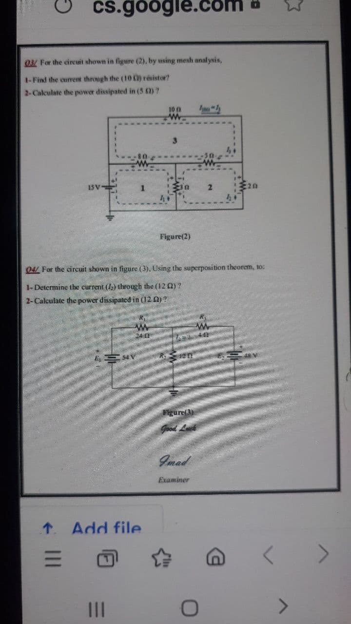
03/ For the cireuit shown in figure (2), by using mesh analysis, 1-Find the current through the (10) résistor? 2-Calculate the power dissipated in (5 2)? 100 3. 15 V 2 44 Figure(2)
Q: Question 2 By using mesh analysis, determine value of all mesh currents for the circuit shown in…
A: We can redraw the circuit as Since there is current source between mesh 1 and mesh 2, so, we can…
Q: For the circuit shown in Figure 1, by using either nodal analysis or mesh analysis, determine:- (i)…
A:
Q: 03/ For the circuit shown in figure (2), by using mesh analysis, 1- Find the current through the (10…
A:
Q: Determine the voltage drop across 1 ohm resistor using Thevenin's Theorem.
A: The solution can be achieved as follows.
Q: 2. Given the circuit in Figure 1, calculate the non-reference voltages, V1 and V2 by using nodal…
A:
Q: Homework 01: Determine the current through the resistor R1 in the circuit shown below using the mesh…
A:
Q: Q1:Determine the Norton equivalent at terminals a-b for the circuit in figure shown. 8 kQ ww 12 v 2…
A:
Q: Question No. 1 a) Using node analysis, determine the unknown node voltages for the circuit shown in…
A:
Q: Q1:- A 15 kVA, 440/230 V, 50 lz, transtormer gave the following test results: Open Circuit (LV side)…
A: In this question, Find the parameters of the transformer. If open and short circuit parameters are…
Q: 4. Consider the circuit in Figure 4. (a) Apply the Nodal Analysis Method to find the branch currents…
A: Apply KCL at node connecting the resistors and current source now using ohms law write the equation…
Q: Mesh Analysis Objective: • Use mesh analysis method to find current values Equipments and…
A: Given, R1=470 ohm R2=330 ohm R3= 220 ohm R4= 330 ohm B1= 12V DC
Q: 2. Determine the current in each resistor in the network figure shown using nodal analysis and…
A:
Q: 03 For the circuit shown in figure (2), by using mesh analysis, 1-Find the current through the (…
A: A per our guidelines, we are supposed to answer only one question.Kindly repost other questions as…
Q: a) For the network shown in the below figure, the value of current needs to be measured in the 10002…
A:
Q: 4.55. A 4 kilo-ohm resistor is placed in parallel with the current source in the circuit. Assume you…
A: Given: A 4 kilo-ohm resistor is connected in parallel with the current source 'i'.
Q: 03/ For the circuit shown in figure (2), by using mesh analysis, 1- Find the current through the (10…
A:
Q: In the circuit below, Use Mesh Current method to calculate: a) The value of the current Io b) The…
A:
Q: A 15 KVA, 440/230 V, 50 Hz, transtormer gave the following test results: Open Circuit (LV side) 250…
A: The open and short circuit parameters of the transformer are given . Find the transformer…
Q: Q # 1: a) Calculate i, and v for the circuit in figure below. (3) b) Show that power dissipated…
A: The circuit in the figure have one depended and one independent source. Voltage across some element…
Q: Assume that the circuit is delivering maximum power to the load resistor R. 1. How much power is…
A: The circuit can be modified as
Q: Q3. For the circuit shown in Figure B, using Mesh Analysis Calculate: i. All loop currents ii.…
A: The solution can be achieved as follows.
Q: 2- Find the Thévenin and Norton equivalent circuits of the circuit shown in figure (2) at the…
A: First we will find out the thevenin equivalent resistance then thevenin equivalent circuit and…
Q: Q3. For the circuit shown in Figure B, using Loop or Mesh Analysis Calculate: i. All loop currents…
A: The solution can be achieved as follows.
Q: Using Thevenin's theorem, calculate the current flowing through the load connected across terminals…
A:
Q: 1. a) For the circuit given in Figure 1, EITHER use the node voltages method to calculate V1, V2, V3…
A:
Q: a) Determine the number of mesh-current equations needed to solve the circuit shown. 4.8 b) Use the…
A: Solution: (b) Modified circuit is, From the circuit, vϕ=3i2-i3 Applying KVL in Loop 1,…
Q: In the circuit shown, a 6-Ohm resistor connected in series to a parallel combination of two…
A: To solve the above problem, we will use Ohm's law and Kirchhoff's law: Ohm's law states that a…
Q: Q3: For the circuit shown in figure (3), use superposition theorem to find the value of the voltage…
A:
Q: Question - 1: In the circuit below, Use Mesh Current method to calculate: a) The value of the…
A: NOTE: Since you have asked multiple questions, we will solve the first question for you. If you want…
Q: QY For the circuit shown in figure (2), by using mesh analysis, 1-Find the current through the (…
A: The solution to both subparts is as follows.
Q: Practice Problem In the circuit shown, calculate the nodal voltages V,V, & V, 2A V3 V ww 102 ww 20 2…
A:
Q: H.W 1 Determine, for the bridge network shown in Figure 12, (a) the value of the single equivalent…
A:
Q: Q1. By first using combinations of resistors, calculate the source current of Circuit 1 and hence…
A:
Q: Dr. Kanaan A. Jalal University of Technology/ Dept. of Electrical Eng. H.W Q) For the circuit shown,…
A:
Q: Considering the circuit in Figure by using mesh or nodal analysis, determine current, i and voltage,…
A: Nodal analysis
Q: For the circuit shown in figure below, find the value of va by using mesh-current method. Calculate…
A:
Q: Q3/ For the circuit shown in figure (9), Using nodal analysis to: 1-determine the current flow in…
A:
Q: For the circuit in Figure 2(a), determine the value of currents In and voltages, Vx, Vy using mesh…
A:
Q: (1) 5K 51 15K 20K I www 10K 5K 5K (2) 12 mA ww ww
A: Redraw the circuit diagram showing the current in each loop,
Q: Question- 1: In the circuit below, Use Mesh Current method to gsakculate: a) The value of the…
A: Circuit diagram is given,
Q: Using Thevenin's theorem, calculate the current flowing through the load connected across terminals…
A:
Q: 3) For the circuit shown in Figure (2), Using Norton's Theorem to calculate the current through 122…
A: The Norton’s resistance can be calculated as, Applying K.C.L at node A,
Q: 0 For the circuit shown in figure (2), by using mesh analysis, 1-Find the current through the ( ,,l;…
A:
Q: 12. Analyse the given circuit to determine the Total resistance as seen from source terminals of the…
A:
Q: For the circuit of figure 3, make use of the test source method as solution method. 3.1) Calculate…
A:
Q: (i) Determine the mesh currents I, I, Is and I, by using mesh analysis. Then calculate the branch…
A:
Q: 02/ For the circuit shown in figure (2), by using mesh analysis, 1- Find the current through the (…
A: a mesh is a loop that does not enclose other loops. KVL, states that “in any closed loop network,…
Q: 2. Determine the current in each resistor in the network figure shown using nodal analysis and…
A:
Q: essment Criteria 1.2,1.3,1.5 ing the circuit below, answer the following questions. Use Kirchhoff's…
A: The circuit is drawn as,
Step by step
Solved in 2 steps with 2 images
- Given a 400sq.m single family dwelling unit to be provided with 230V, 1-phase, 2-wire service, and having the following loads: 2-1.5hp A/C, 2-1.0hp A/C, 1-0.5hp water pump, 4-800W water heater, 2-6kW electric range and 2-1kW microwave oven, determine the total connected load in volt-ampere (VA). Write your answer in numerical format without decimal places.In a house there is a three-wire system configured as follows: A refrigerator with an impedance of (10 + j 10) Ω is connected to line L1 and to a neutral. And to line L2 and neutral all the lighting in the house consisting of 10 luminaires of 20 W each. In addition, there is a 240 V dryer that consumes 8 kW connected between the two lines. Calculate current in line L1, line L2 and neutral total power consumed Problem was Initially stated in spanish, i will add it in case it works. En una vivienda se tiene un sistema trifilar configurado de la siguientemanera. Se tiene conectada a la línea L1 y a neutro una refrigeradora con impedancia de (10 + j 10)Ω y a la línea L2 y neutro toda la iluminación de la casa consistente en 10 luminarias de 20 W cadauna. Además, se tiene una secadora a 240 V que consume 8 kW. Calcule a) corriente de la línea L1 yde la línea L2 y de neutro b) potencia total consumida.Given a 400sq.m single family dwelling unit to be provided with 230V, 1-phase, 2-wire be service, andhaving the following loads: 2-1.5hp A/C, 2-1.0hp A/C, 1-0.5hp water pump, 4-800W water heater, 2-6kWelectric range and 2-1kW microwave oven, determine a) the total connected load, b) the total demand load,c) the overall %demand factor, d) the size of THW feeder conductor, ground wire and IMC conduit, e) therating of feeder overcurrent protection using inverse time circuit breaker
- For a 220V, 60Hz single phase voltage controller is used for controlling flow of power in to a circuit consisting load of Xl =12 ohms and R=5 ohms. Which of the following represents the correct value of the maximum power and power transfer? (a) Pmax=9.68 kW, p.f =0.6 (b) Pmax=3.72 kW, p.f =0.6 (a) Pmax=9.38 kW, p.f =0.38 (a) Pmax=1.43 kW, p.f =0.38Derive conditions for economics dispatch when generating stations are connected in parallelA single phase a. C distributor AB 300mts long if fed from end A is loaded as under a) 100amps at 0.707 p.f lagging 200mts from pointA(b) 200amps at 0.8p.f lagging 300mts from point A. The total resistance and the Reactance and the distributor is0. 2ohms and0. 1ohms per km respectively. Calculate the total voltage drop in the distributor. The load power factors refer to the voltage at the far end
- A 2000 KVA, 6600/400V , Delta/Star was performed with short circuit and Open circuit test with the following results:O.C. Test : 400V, 150A and 15kwS.C. Test: 400V, 175A and 17kwDetermine the percent impedance drop for resistance, reactance and impedance. Also calculate for the efficiency at half load, 0.85pf lagging and full load, 0.8pf leading.A 2000 KVA, 6600/400V , STAR/Delta was performed with short circuit and Open circuit test with the following results: O.C. Test : 400V, 150A and 15kw S.C. Test: 400V, 175A and 17kw Determine the percent impedance drop for resistance, reactance and impedance. Also calculate for the efficiency at half load, 0.80pf lagging and full load, 0.85pf leading.Applying the mesh analysis method, for the resolution of the following circuit, determine:a) The actual magnitude and direction of the current in each of the loops of the circuit.b) Redraw the circuit and indicate the magnitude and direction of the currentsresults found.c) The voltage (with polarity) across resistors ?2 and ?3.Note: For your procedure to be valid, you must clearly state the addressassumption of the currents according to the indicated mesh numbering (I, II, III), the polarity in eachone of the elements, detailed approach and simplification of each of the equations ofmesh, the system to be solved as a result of executing the method and those requested in each subsectionformer.
- Use Mesh Current MethodDetermine the Norton equivalent of the following circuit, ISC and RN . Calculate the load current IL for RL = 10 ohm. R1 = R4 = 2 ohm , R2 = 6 ohm, R3 = 3 ohm, and R5 =6 ohm. The network is supplied with a current source of I1 = 1A.Q 1) For the circuit shown blow, Use the node-voltage method of circuit analysis to find the branch currents. 1.The branch current ??is equal to? * 2.The branch current ?? is equal to? * 3.The branch current ?? is equal to? *