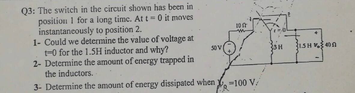
03: The switch in the circuit shown has beeln TII position 1 for a long timc. At t = 0 it moves instantaneously to position 2. 1- Could we determine the value of voltage at t=0 for the 1.5H inductor and why? 2- Determine the amount of energy trapped in the inductors. . 3- Determine the amount of energy dissipated when 10 S0 V 3H 1.5 H 40 N =100 V.


Q: 2. 7.2 In the circuit shown the switch makes contact withposition b just before breaking contact…
A: To calculate the percentage of the initial energy stored in the inductor is dissipated in the 90 Ω…
Q: IL 1H 20 Q 20 Q 48 V 10 Q Consider the circuit above. The switch has been closed for a very long…
A: given : inductor value is 1 Henry Supply is 48 volt. Calculate: iL ,io,VL for t>O
Q: Q2/ For the network shown in figure (Q2), the switch has been open for a long time before closing at…
A: Given data: L=20 mH
Q: In the circuit shown in the figure, the inductor has inductance L = 2.50 H and negligible internal…
A: According to the question we have to find the value currents in each branch at both conditions t=0…
Q: R a Vb b Ve
A:
Q: In the circuit shown in Figure, the switch is activated at t = 0 s for position 2 of position 1,…
A: Case 1: When switch is connected to position 1 Although it is given that switch is connected to…
Q: R4 S2 S1 iT R5 R6 +HE + RIZ ic2 C3 VT C2: C1 V1 R2 SR3
A:
Q: The triangular current pulse shown in the provided figure is applied to a 500 mH inductor. A.) Use…
A:
Q: 9 THE FOLLOWING QUESTIONS ARE BASED ON THE INFORMATION GIVEN HERE. R2 The emf source, E = 2.1 V, of…
A:
Q: The two parallel inductors shown are connected across the terminals of a black box at t=0. The…
A: Since you have posted a question with multiple sub-parts, we will solve first three sub-parts for…
Q: Q2/ For the network shown in figure (Q2), the switch has been open for a long time before closing at…
A:
Q: Q.9: The initial charge on the capacitor is 100µCoulomb: 1. Write the transient curent equation. 2.…
A: Using kvl obtain the differential equation governing the system. Solve the differential equation to…
Q: (a) The current flows through a 1mH inductor is given by i(t) = 20cos 100t mA Find the expression…
A:
Q: = 3V E2 = 1V R1 R2 C = 1 µF E1 R R2 2, ||
A: We will use here capacitor charge formula to calculate charge on capacitor .
Q: The capacitor in the circuit shown is charged to 20 V at the time the switch is closed. If the…
A: Given data: The voltage across capacitor is: 20 V The below circuit at t > 0, The value of…
Q: [Q3] The voltage across a 5 µF capacitor is known to be as follows: -2500 Ve = 500te V. for t 0. a)…
A:
Q: Q2: The swien n the circuit shown has been in position 1 for a long time. At t 0 it moves…
A: "Since you have posted a question with multiple sub-parts, we will solve first three sub-parts for…
Q: The switch in the circuit in figure 1 has been in position 1 for a long time. At t = 0 it moves…
A: Since you have posted a question with multiple sub-parts, we will solve the first three sub-parts…
Q: In determining an expression for i, (t) fort > 0 (i) Draw the circuit diagram for t 0 Calculate the…
A: Note: As per the policy we can solve only 3 sub-parts of single question, please re-upload the…
Q: Q2/ For the network shown in figure (Q2), the switch has been open for a long time before closing at…
A:
Q: The voltage across a 300mH inductor is given by v(t) = cos2(377t). Determine the current i at t = 4s…
A: In this question, The voltage across a 300mH inductor is given by v(t) = cos2(377t). Determine the…
Q: A resistance of 20 Q and an inductance L are connected in series with a constant voltage of 100V.…
A:
Q: Q3: The switch in the circuit shown has been in position 1 for a long time. At t=0 it moves…
A:
Q: The switch in the circuit shown has been in position I for a long time. Att0 it moves…
A: 1) For t<0 inductor iL10ο=5010=5AmpiL20ο=0 Amp For t≥0 t1=L140 t2=L240 = 340 =…
Q: a) Write the mathematical expressions for ve, VRi, and ic after the switch is thrown into position…
A: The switch is thrown to position '1' at a time t=0 s as shown in the figure below.
Q: Given is the following circuit: Switch loc (1 R Initially, there is no current in the inductor. The…
A: From the question this is given that initially, there is no current in the inductor. Now, the switch…
Q: 6. In the circuit below L = 0.20 H, R1 = 4.0 N, R2 = 5.0 2, and ɛ = 3.0 V. The switch closes at time…
A: Given data, L1=0.20AR1=4.0ΩR2=5.0Ωε=3.0V The given circuit is shown below, Applying KCL in the…
Q: Q2. The switch in the circuit shown in Figure 3 has been closed for a very long time and is opened…
A: Disclaimer: Since you have asked multipart questions, we will solve the first three subpart for…
Q: 4. Based on the figure above, sketch graphs as a function of time t > 0, when the inductance of the…
A: To solve above question, one should understand the behavior of Inductor and capacitor in DC circuit.…
Q: Unknown Capacitance: For the circuit below, the switch has been closed for a = 0, the switch becomes…
A:
Q: The switch below has been closed for a long period of time and is opened at t=0. a) Find the ENERGY…
A: Since you have posted a question with multiple sub-parts, we will solve first three sub-parts for…
Q: R2 R3
A: In d.c. analysis, under steady state condition a capacitor will behave as OPEN CIRCUIT. The detailed…
Q: instantaneously to position 2. Determine, 1- The current it) of each inductor for 20. 2- The…
A: Please find your answer below in step 2. As per Bartleby guidelines I can not give answer of more…
Q: For the network shown in figure (Q2), the switch has been open for a long time before closing at…
A: Transient is the time taken for an electrical circuit to settle down to it's steady state from a…
Q: t=0 R1 R3 В ww 1= 0 INT 1 INT 2 V1 R2 V 30 V
A:
Q: In the circuit shown in the figure, switch S is closed at t = 0. a) What is the current in the…
A: Inductor: It is a passive two-terminal electrical component and measured in Henry (H). When…
Q: The switch in Figure Q2(b) circuit has been closed for a long time. At t = 0 s, the switch is…
A: The solutions are
Q: QI/ For the network shown in figure (Q), the switch has been in position "a" for a long time. At…
A: Before time to=0 second Switch at position a. For long time, inductor act as short circuit. At time…
Q: 4. The capacitance of C1 is 2F, the capacitance of C2 is 2F, the capacitance of C3 is 1F, and the…
A: We need to find out charge and voltage across capacitor in given circuit
Q: Given that the electric circuit shown below is at steady state, find the energy stored in each…
A: We have given that the electric circuit shown is at steady state find the energy stored in each…
Q: (e) A 2 H inductor is known to have current i(t) (in Amperes) as given in the figure. Assuming this…
A: Since you have asked multiple questions in a single request, we will be answering only the 1st…
Q: 4. If the current flowing through a 75 mH inductor has the waveform shown in figure 3, (a)sketch the…
A: In this question, We need to draw the voltage across the inductor V= L di/dt Where current I(t)…
Q: the circuit shown in the Figure, the switch is activated at t = 0 s from position 1 to position 2…
A: In this question we will find current through inductor...
Q: Problem #1: If the current flowing through a 75mH inductor has the waveform shown below. (a)…
A: (a) Calculate the equation of current from the graph using the straight-line method for the time…
Q: 652 Q.36: The switch in the circuit shown in figure beside has been in position "a" for a long time,…
A:
Q: In the figure below, after sitting for a long time in position a, the switch in the circuit was…
A: The Transient Equation of a series RL circuit is given as: i(t)=ist(t)+itr(t)⇒i(t)=I(∞)+I(0)-I(∞)…

Step by step
Solved in 2 steps with 2 images

- A 10-mH inductor has a parasitic series resistance of R s =1 Ω, as shown in FigureP3.68.a. The current is given by i( t )=0.1 cos( 10 5 t ). Find v R ( t ), v L ( t ), and v(t). In thiscase, for 1-percent accuracy in computing v(t), could the resistance be neglected?b. Repeat if i( t )=0.1 cos( 10t ).In the circuit shown in the figure, the inductor has inductance ?=3.50 HL=3.50 H and negligible internal resistance. The battery has a voltage of ?b=16.0 VVb=16.0 V and is connected in series to a resistor of resistance ?1=14.0 Ω.R1=14.0 Ω. A second resistor has a resistance of ?2=145 Ω.R2=145 Ω. The switch ?S has been open for a long time. At time ?=0,t=0, the switch is closed. What is the current ?b,0Ib,0 through the battery, the current ?2,0I2,0 through resistor ?2,R2, and the current ?L,0IL,0 through the inductor at ?=0.t=0. What is the current ?b,∞Ib,∞ through the battery, the current ?2,∞I2,∞ through resistor ?2,R2, and the current ?L,∞IL,∞ through the inductor long after the switch is closed (i.e., ?=∞).1. For the network shown in Figure 1:(a) Determine the mathematical expressions for the variation of the current in the inductor following the closure of the switch at t = 0 on to position 1.(b) When the switch is closed on to position 2 at t = 100 ms, determine the new expression for the inductor current and for the voltage across R.(c) Plot the current waveforms for t: 0 to t = 200 ms.
- IN THE CIRCUIT SHOWN, CONSIDER THAT V1=20 VDC, R1=1000 Ω, R2=3000 Ω, R3=3500 Ω AND C=1 mF.DETERMINE:A) THE TIME IT TAKES FOR THE CAPACITOR TO REACH ITS FINAL VALUE (5T), WHEN SWITCH 2 (INT 2) IS IN POSITION A AND SWITCH 1 (INT 1) IS CLOSED AT t=0,B) THE ENERGY STORED BY THE CAPACITOR ONCE IT HAS BEEN FULLY CHARGED WITH THE SAME POSITION OF SWITCHES AS ITEM A)C) ONCE THE CAPACITOR HAS BEEN FULLY CHARGED WITH SWITCH 1 CLOSED, SWITCH 2 MOVES POSITION (GOES TO B) AT A NEW t=0. NOW DETERMINE THE VALUE OF THE VOLTAGE ON THE CAPACITOR AT t=3.5 SECONDSQ2. For the RL circuit, shown in figure (1), the switch has been in position “a” for a long time, before switching to position “b”, at t = 0. Find a) a time-expression for the current through the inductor, i(t), for t > 0, b) the values of v(0- ), v(0+ ), and v(∞), and c) the powers dissipated in the 3-Ω resistor, at t = 3 ms.2. 7.2 In the circuit shown the switch makes contact withposition b just before breaking contact with position a. This is known asa make-before-break switch and it ensures that the inductor current iscontinuous. The interval of time between “making” and “breaking” isassumed to be negligible. The switch has been in the a position for along time. At t=0 the switch is thrown from position a to position b.4. d) What percentage of the initial energy stored in the inductor isdissipated in the 90 Ω resistor 1 ms after the switch is thrown fromposition a to position b?
- The switch in the circuit below has been in position a for a long time. At time t = 0 the switch is thrown to position b. You are given the data: Vb = 24 V, C = 10 μF. Vc is the voltage across the capacitor. If the charge on the capacitor at time t =0.3 msec after the switch is thrown is 53.6 μC, what is the value of the resistor R? a) 40 Ω b) 0 Ω c) 20 Ω d) Not enough information.Given the circuit below with the switch closed for a long time, then opening at t=0, and with the values R1=129KΩ, R2=128KΩ, R3=103KΩ, calculate the time constant, τ, for the capacitor voltage solution for at t >0.The two parallel inductors shown are connected across the terminals of a black box at t=0. The resulting voltage v for t>0 is known to be 12e−t V. It is also known that i1(0)=2 A and i2(0)=4 A. a. Replace the original inductors with an equivalent inductor and find i(t) for t≥0. b. Find i1(t) for t≥0. c. Find i2(t) for t≥0. d. How much energy is delivered to the black box in the time interval 0≤t<∞? e. How much energy was initially stored in the parallel inductors? f. How much energy is trapped in the ideal inductors? g. Show that your solutions for i1 and i2 agree with the answer obtained in (f).
- A 150-volt electromotive force is applied to an RC-series circuit in which the resistance is 1500 ohm and the capacitance is 5 micro Farad (uF). If q(0)=0, find the charge and current at t=0.005 s. charge: q = micro Farad (uF) current: i = milli ampere (mA) Determine the charge as t approaches infinity. charge: q= micro Farad (uF)For the capacitor network shown in Figure(Q2a) above (which has reachedsteady state i.e. on for a very long time), calculate:i. The total capacitance, CT , for the entire networkii. The voltage across capacitor C2iii. The total charge stored across capacitor C2iv. The energy stored in capacitor C2The figure shows an electrical circuit with an ideal source ε1 = 12 [V], a real source ε2 = 9 [V] and r1 = 1 [Ω], eight resistors and two capacitors. Switches A and B areThey are originally open and the charge on the capacitors is zero. If at t = 0 [s] switch A opens and switch B closes, determine:d) The potential difference of resistor R8 at t = 2.6 [s].e) The time required for the potential difference of the equivalent capacitor to reach the maximum possible value. Justify your answer.