the circuit shown in the Figure, the switch is activated at t = 0 s from position 1 to position 2 (since he spent a lot of time in position 1). Find the expression of the current in the inductor for t>
the circuit shown in the Figure, the switch is activated at t = 0 s from position 1 to position 2 (since he spent a lot of time in position 1). Find the expression of the current in the inductor for t>

Power System Analysis and Design (MindTap Course List)
6th Edition
ISBN:9781305632134
Author:J. Duncan Glover, Thomas Overbye, Mulukutla S. Sarma
Publisher:J. Duncan Glover, Thomas Overbye, Mulukutla S. Sarma
Chapter2: Fundamentals
Section: Chapter Questions
Problem 2.1P: Given the complex numbers A1=630 and A2=4+j5, (a) convert A1 to rectangular form: (b) convert A2 to...

Related questions

Question
In the circuit shown in the Figure, the switch is activated at t = 0 s from position 1 to position 2 (since he spent a lot of time in position 1). Find the expression of the current in the inductor for t> 0.
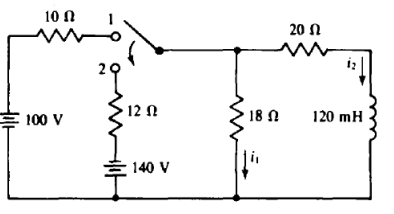
Transcribed Image Text:10 N
20 N
100 V
12 N
18 N
120 mH
140 V
Expert Solution
This question has been solved!
Explore an expertly crafted, step-by-step solution for a thorough understanding of key concepts.

Step by step
Solved in 5 steps with 4 images

Knowledge Booster


Learn more about
Need a deep-dive on the concept behind this application? Look no further. Learn more about this topic, electrical-engineering and related others by exploring similar questions and additional content below.Recommended textbooks for you
Power System Analysis and Design (MindTap Course …
Electrical Engineering
ISBN:
9781305632134
Author:
J. Duncan Glover, Thomas Overbye, Mulukutla S. Sarma
Publisher:
Cengage Learning
Power System Analysis and Design (MindTap Course …
Electrical Engineering
ISBN:
9781305632134
Author:
J. Duncan Glover, Thomas Overbye, Mulukutla S. Sarma
Publisher:
Cengage Learning