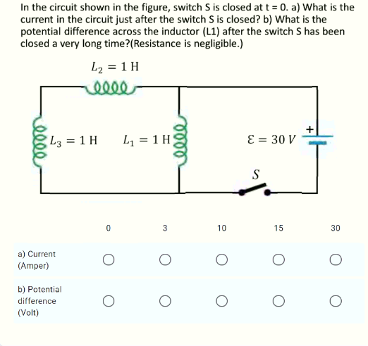
In the circuit shown in the figure, switch S is closed at t = 0. a) What is the current in the circuit just after the switch S is closed? b) What is the potential difference across the inductor (L1) after the switch S has been closed a very long time?(Resistance is negligible.) L2 = 1 H L3 = 1 H L1 = 1 H) ɛ = 30 V S lell
Q: 2. 7.2 In the circuit shown the switch makes contact withposition b just before breaking contact…
A: To calculate the percentage of the initial energy stored in the inductor is dissipated in the 90 Ω…
Q: A potential difference V(t) = V0sin ωt ismaintained across a parallel-plate capacitor…
A: Given Vt=V0sinωt a) Calculating Ires(t) Ires(t)=V(t)RIres(t)=V0sinωtR
Q: image480
A:
Q: R a Vb b Ve
A:
Q: In the circuit shown in Figure, the switch is activated at t = 0 s for position 2 of position 1,…
A: Case 1: When switch is connected to position 1 Although it is given that switch is connected to…
Q: The triangular current pulse shown in the provided figure is applied to a 500 mH inductor. A.) Use…
A:
Q: 9 THE FOLLOWING QUESTIONS ARE BASED ON THE INFORMATION GIVEN HERE. R2 The emf source, E = 2.1 V, of…
A:
Q: (S/3x) mF i(1) 42. + R2 R: 3v. (1) (1/10n) H3.
A: Note: Since you have posted a question with multiple subparts, we will solve the first three…
Q: The two parallel inductors shown are connected across the terminals of a black box at t=0. The…
A: Since you have posted a question with multiple sub-parts, we will solve first three sub-parts for…
Q: For the circuit in Figure Q1(b), under DC condition, find the voltage across the capacitor, Ve and…
A:
Q: In the circuit diagram R1 = 1760 Ω, R2 = 3130 Ω, C1 = 2.9 μF, C2 = 5.7 μF, and ℰ = 12 V. The switch…
A: Note: We are authorized to answer three subparts at a time since you have not mentioned which part…
Q: Write a small essay about discharging capacitor then: For the circuit shown, the switch was open for…
A:
Q: 2. The equation of electric charge on the capacitor is related to the equation of current strength…
A: Given the differential equation in RLC circuit as : Ld2qdt2+Rdqdt+1Cq=E(t) Given: R=10 Ω, L=0.25 H,…
Q: Q2: The swien n the circuit shown has been in position 1 for a long time. At t 0 it moves…
A: "Since you have posted a question with multiple sub-parts, we will solve first three sub-parts for…
Q: (a) For the circuit shown in Figure 3.1, what is the time constant, r? t=0 10 ko 3 kN 3 μ 10 V…
A:
Q: ) THE FOLLOWING QUESTIONS ARE BASED ON THE INFORMATION GIVEN HERE. R C n the circuit shown in the…
A:
Q: The inductors in the circuit shown are initially charged and are connected to the Black Box at time…
A: Given:- currents i10=4A, i2(0)=-3A, voltage v(t)=50e-200tmV (a) We have to find the initial energy…
Q: (9) THE FOLLOWING QUESTIONS ARE BASED ON THE INFORMATION GIVEN HERE. R2 The emf source, E = 4.7 V,…
A:
Q: A 150-volt electromotive force is applied to an RC-series circuit in which the resistance is 1500…
A:
Q: Q1 of 2) The circuit given has reached steady state before the switch closes at time t = 0. (a)…
A:
Q: Given the following circuit, where V = 12 volts, R = 3200, C = 0.001 F, assuming that the switch…
A:
Q: A3 Two coils A and B have, initially, a mutual inductance of 250 mH, and the current in coil A is 2…
A: In this question we need to find a average value of voltage induced in coil B during 0.2 sec
Q: RC Circuit For the circuit in Figure 3 a switch is left open for a long time and then closed at time…
A:
Q: R2 HERE. R1 The emf source, E = 2,2 V, of the circuit shown in the figure has negligible internal…
A: According to question we have to find the value of (a) time constant (b) charge Q
Q: 6. In the circuit below L = 0.20 H, R1 = 4.0 N, R2 = 5.0 2, and ɛ = 3.0 V. The switch closes at time…
A: Given data, L1=0.20AR1=4.0ΩR2=5.0Ωε=3.0V The given circuit is shown below, Applying KCL in the…
Q: Consider the circuit shown in the figure below, where C, = 8.00 µF, C, = 8.00 µF, and AV = 22.0 V.…
A: The given circuit is as shown below :
Q: A potential difference AV is applied across the combination of capacitors shown in the figure, where…
A: The voltage across the series capacitors are calculated as Vc1=∆V*93=3∆VVc2=∆V*96=1.5∆V
Q: R2 R3
A: In d.c. analysis, under steady state condition a capacitor will behave as OPEN CIRCUIT. The detailed…
Q: The inductors in the circuit shown are initially charged and are connected to the Black Box at time…
A: Given:- L1=5H;L2=20Hi1(0)=4A;i2(0)=-3A and V(t)=50e-200tmv
Q: Q1) Considering the same circuit, only with the switch thrown from b to a at time t= 0 after having…
A: As per the guidelines of Bartleby we supposed to answer 1st three subparts of the question for…
Q: A 150-volt electromotive force is applied to an RC-series circuit in which the resistance is 1500…
A:
Q: The emf source, E, of the circuit shown in the figure has negligible internal resistance. The…
A: Given circuit: Source emf has negligible internal resistance. Resistors R1=7.1 ΩR2=2.8 Ω…
Q: Consider the circuit below. Each capacitor has 51 nF capacitance. R1 and R2 each have 132 kQ of…
A: According to the question Given, all the values of R1, R2, C1, C2 and battery V. And we have to find…
Q: A circuit consists of a battery with E=50.0 V, two resistors R,=30.02, R,=15.02, and an inductor…
A: Dear student as per our guidelines we are supposed to solve only one question in which it should…
Q: capacitor consists of two circular plates of radius a separated by a distance d (assume d a. (A)…
A:
Q: A potential difference AV is applied across the combination of capacitors shown in the figure, where…
A: The mathematical expression for the energy stored in the capacitor is given by: U=12Q2C Here, U…
Q: FACULTY OF SCIENCES DEPARTMENT OF PHYSICS QUESTION NO. 2: MANDATORY/DOPTIONAL / BONUS In the figure,…
A: Given- C =0.4 uF ε= 20 V R1 = 10 k ohm R2= 15 k ohm
Q: (a) Determine the equilibrium charge on the capacitor in the circuit shown as a function of R. (b)…
A: Since we only answers up to 3 sub-parts, we will answer the first 3. Please resubmit the question…
Q: PROBLEM 2: In the circuit shown, capacitor C1 has an initial charge qo = 300 × 10-6 Coulombs. If the…
A:
Q: Question a. What is the initial voltage, Ve, in the сарacitor? b. What is the equivalent resistance…
A:
Q: a. What is the governing equation for the current through the inductor, i(t)? What is the initial…
A: Since you have posted a question with multiple sub-parts, we will solve the first three sub-parts…
Q: (e) A 2 H inductor is known to have current i(t) (in Amperes) as given in the figure. Assuming this…
A: Since you have asked multiple questions in a single request, we will be answering only the 1st…
Q: Consider an RLC circuit with resistance 5 ohms, inductance 0.05 henrys, capacitance 0.006 farads,…
A: Question b is solved using given initial conditions
Q: Two coils A and B have, initially, a mutual inductance of 250 mH, and the current in coil A is 2 A.…
A: Given data, The value of current (i) = 2 A The value of time(T) = 0.2 sec
Q: 3. (a) State the DE model of RC series circuit. (b) A 100-volt electromotive force is applied to an…
A: Transient represent sudden change in the state of a network or circuit which are indicated by…
Q: the circuit shown in the Figure, the switch is activated at t = 0 s from position 1 to position 2…
A: In this question we will find current through inductor...
Q: 652 Q.36: The switch in the circuit shown in figure beside has been in position "a" for a long time,…
A:
Q: In the figure below, after sitting for a long time in position a, the switch in the circuit was…
A: The Transient Equation of a series RL circuit is given as: i(t)=ist(t)+itr(t)⇒i(t)=I(∞)+I(0)-I(∞)…
Step by step
Solved in 3 steps with 1 images
- The circuit shown is at steady state before the switch closes. The inductor currents are both zero before the switch closes (i1(0) = i2(0) = 0). The voltage across the 2H-inductor is 4e-5t V for t > 0, otherwise 0V for t < 0. (a) Determine the inductor currents i1(t) and i2(t) for t ≥ 0. (b) Determine the energy stored by each inductor 200ms after the switch closes. (c) In the equivalent inductor (for the parallel inductors) determine the (i) current and the (ii) energy stored for 200 ms after the switch closes. Answer: 0.4(1 − e−5t) A, 0.1(1 − e−5t) A, 16.0mJ, 63.9mJ, 316mA, 79.9mJIf a circuit consisting of a resistor and induction in series has a DC current of 500mA following through it, andthe switch in the circuit is suddenly open. What is the Inductive spike voltage induced in the inductor if thecurrent reaches 0 A in 200 x 10-6 sec (200 micro second) and the Inductance, L =100mH? Hint: { Vemf =L di/dt}a) 250 V b) 500 V c) 1000V d) 10 VFrom the given circuit. Switch S1 is in position A switch S2 is open. Both switches are in these states for a very long time. At t=0, switch S1 moves from position A to B while switch S2 remains open. 10ms after switch S1 moves to position B, switch S2 is closed and remains closed for 20ms only. ANSWER THE FOLLOWING: a.) Expression for the inductor current for 0 ≤ ? < 10??b.) Expression for the inductor current for 10?? ≤ ? < 30?? and 30?? ≤ ? < ∞c.) What is the time (in ms) after switch S1 moves to position B is the current in the inductor equivalent to 30% of the initial value (at ?=0).
- In the circuit shown in the figure, both switches are closed for a long time. At t = 0, the 1st switch is opened. After 35 ms, the 2nd switch opens. According to this; a) Find the current expression iL (t) of the circuit for 0 <= t <= 35 ms.b) Find the current expression iL (t) of the circuit for t> = 35 ms.c) Find what% of the energy consumed in the 18 ohm resistor is the initial energy stored in the 150mH inductor?d) What is the amount of energy consumed in 3 ohm resistor,% of the initial energy stored in 150mH inductor?e) What is the amount of energy consumed in the 6 ohm resistor,% of the initial energy stored in the 150mH inductor?In the circuit shown in Figure, the switch is activated at t = 0 s for position 2 of position 1, where you've spent a lot of time. Find the expression of the current in the inductor for t> 0.In the circuit of the figure, the switch S has been in position a for a long time; when the current through the inductor is maximum, the switch changes to position b (this instant is taken as t = 0). If the current source is iS(t) = 2.1213 cos (100πt + π/ 4). Determine: i) the value of R2 so that at t = 4 mS the current iL (t = 4mS) = 1 A. ii) The expression for the inductor current iL(t) t> 0 iii) the value of iL(t) at t = 0. iv) the expression of the inductor voltage vL(t) t> 0. v) the value of vL(0).
- In the circuit below the switch is in positionafor a long period of time. Att=0the switch moves from position a to position b. The switch is designed such that the inductor current is continuous when moving from positionato position b. (a) Find the expression fori(t)fort≥0 (b) What is the initial voltage across the inductor just after the switch moved to positionb? (c) Does this initial voltage make sense? (d) How long does it take for the inductor voltage to equal24 Vafter the switch has been movedIn the figure below, the switch is open for a long time and the switch is closed at t = 0 .a) Find the initial conditions for t = 0? (Vc(0)=?,iL(0)=?)b) Find for the inductor current for t >=0 ?(iL(t)=?)c) Find the capacitor voltage and current through the switch (isw) for t >=0 ? (Vc(t)=?)What is a Linear Circuit? Simply we can say that the linear circuit is an electric circuit (Links to an external site.) and the parameters of this circuit are resistance, capacitance, inductance and etc are constant. Or we can say the parameters of the circuits are not changed with respect to the voltage and current is called the linear circuit. What is a Non-Linear Circuit? The non-linear circuit is also an electric circuit and the parameters of this circuit differ with respect to the current and the voltage. Or in the electric circuit, the parameters like waveforms, resistance, inductance and etc are not constant is called as Non- linear circuit. Question: Is it possible to apply superposition theorem to nonlinear circuit? If yes, why? and if no, why?
- In the circuit shown below, the switch has been open a long time and the circuit is initially in steady-state. At t=0, the switch is closed. R1=0.2Ω, and R2=0.4Ω. The batteries have EMFs E1=1V and E2=3V. The capacitor has capacitance 10 μF. Hint: What is the voltage on the capacitor just before the switch is closed? Note that there is a voltage drop over the open switch. a) What is the voltage over the capacitor before the switch is closed? b) Draw the Thevenin equivalent circuit as seen by the capacitor. c) What is the time constant for charging the capacitor? d) What is the voltage on the capacitor as a function of time?Given circuit, capacitor voltage is at 0 V with switch SW1 open. At time t0, switch SW1 is closed. At time t0, what is the voltage v? What is the voltage v at time infinity? At time t0, what is the current through R2? What is the current through R2 at time infinity?A circuit consists of switches that open or close at t=0, resistances, dc sources, and a single energy storage element, either an inductance or a capacitance. We wish to solve for a current or a voltage x(t) as a function of time for t≥0. Write the general form for the solution. How is each unknown in the solution determined?