1 Tension, Compression, And Shear 2 Axially Loaded Members 3 Torsion 4 Shear Forces And Bending Moments 5 Stresses In Beams (basic Topics) 6 Stresses In Beams (advanced Topics) 7 Analysis Of Stress And Strain 8 Applications Of Plane Stress (pressure Vessels, Beams, And Combined Loadings) 9 Deflections Of Beams 10 Statically Indeterminate Beams 11 Columns Chapter1: Tension, Compression, And Shear
Chapter Questions Section: Chapter Questions
Problem 1.3.1P: Find support reactions at A and B and then calculate the axial force N. shear force J and bending... Problem 1.3.2P: Find support reactions at A and B and then calculate the axial force N, shear force V, and bending... Problem 1.3.3P: Segments AB and BC of beam ABC are pin connected a small distance to the right of joint B (sec... Problem 1.3.4P: Segments A B and BCD of beam A BCD are pin connected at x = 4 m. The beam is supported by a sliding... Problem 1.3.5P: Segments AB and BCD of beam ABCD are pin connected at x = 10 ft. The beam is supported by a pin... Problem 1.3.6P: Consider the plane truss with a pin support at joint 3 and a crtica1 roller support at joint 5 (see... Problem 1.3.7P: A plane truss has a pin support at A and a roller support at E(see figure). (a) Find reactions at... Problem 1.3.8P: A plane truss has a pin support at F and a roller support at D (see figure). (a) Find reactions at... Problem 1.3.9P: Find support reactions at A and B and then use the method of joints to find all member forces. Let c... Problem 1.3.10P: Find support reactions at 4 and Band then use the method of joints to find all member forces. Let b... Problem 1.3.11P: Repeat 1.3-9 but use the method of sections go find member forces in AC and BD. Problem 1.3.12P: Repeat 1.3-10 but use the method of sections to find member forces in AB and DC. Problem 1.3.13P: A space truss has three-dimensional pin supports at joints 0, B, and C, Load P is applied at joint A... Problem 1.3.14P: A space truss is restrained at joints O, A. B. and C, as shown in the figure. Load P is applied at... Problem 1.3.15P: 1.3-15 A space truss is restrained at joints A, B, and C, as shown in the figure. Load 2P is applied... Problem 1.3.16P: A space truss is restrained at joints A, B. and C, as shown in the figure. Load P acts in the +z... Problem 1.3.17P: A stepped shaft ABC consisting of two solid, circular segments is subjected to torques T}and... Problem 1.3.18P: A stepped shaft ABC consisting of two solid, circular segments is subjected to uniformly distributed... Problem 1.3.19P: A plane frame is restrained al joints A and C, as shown in the figure. Members AB and BC are pin... Problem 1.3.20P: A plane Frame is restrained at joints A and D, as shown in the figure. Members AB and BCD are pin... Problem 1.3.21P: Find support reactions at A and D and then calculate the axial force N, shear force V, and bending... Problem 1.3.22P: Find support reactions at A and D and then calculate the axial force N. shear force 1 and bending... Problem 1.3.23P: ,3-23 A 200-lb trap door (AD) is supported by a strut (BC) which is pin connected to the door at B... Problem 1.3.24P: A plane frame is constructed by using a pin connection between segments ABC and CDE. The frame has... Problem 1.3.25P: A plane Frame with pin supports at A and E has a cable attached at C, which runs over a... Problem 1.3.26P: A plane frame with a pin support at A and roller supports at C and £ has a cable attached at E.... Problem 1.3.27P: A 150-lb rigid bar AB. with friction less rollers al each end. is held in the position shown in the... Problem 1.3.28P: A plane frame has a pin support at A and roller supports at C and E (see figure). Frame segments A... Problem 1.3.29P: A special vehicle brake is clamped at O when the brake force P1 is applied (see figure). Force P1=... Problem 1.3.30P: Space frame A BCD is clamped at A, except it is Free to translate in the .v direction. There is also... Problem 1.3.31P: Space Frame ABC is clamped at A, except it is free to rotate at A about the x and y axes. Cables DC... Problem 1.3.32P: A soccer goal is subjected to gravity loads (in the - z direction, w = 73 N/m for DG, BG, and BC; w... Problem 1.3.33P: An elliptical exerciser machine (see figure part a) is composed of front and back rails. A... Problem 1.3.34P: A mountain bike is moving along a flat path at constant velocity. At some instant, the rider (weight... Problem 1.4.1P: A hollow circular post ABC (see figure) supports a load Pt= 1700 lb acting al the top. A second load... Problem 1.4.2P: A circular nylon pipe supports a downward load PA= 10 kN. which is uniformly distributed around a... Problem 1.4.3P: A circular tube AB is fixed at one end and free at the other end. The tube is subjected to axial... Problem 1.4.4P: A force P of 70 N is applied by a rider to the front hand brake of a bicycle ( P is the resultant of... Problem 1.4.5P: A bicycle rider wants to compare the effectiveness of cantilever hand brakes (see figure part a)... Problem 1.4.6P: A circular aluminum tube with a length of L = 420 mm is loaded in compression by forces P (see... Problem 1.4.7P: The cross section of a concrete corner column that is loaded uniformly in compression is shown in... Problem 1.4.8P: A car weighing 130 kN when fully loaded is pulled slowly up a steep inclined track by a steel cable... Problem 1.4.9P: Two steel wines support a moveable overhead camera weighing W = 28 lb (see figure part a) used For... Problem 1.4.10P: A long re Lai nine: wall is braced by wood shores set at an angle of 30° and supported by concrete... Problem 1.4.11P: A pickup truck tailgate supports a crate where Wc= 150 lb. as shown in the figure. The tailgate... Problem 1.4.12P: Solve the preceding problem if the mass of the tailgate is MT— 11 kg and that of the crate is hic—... Problem 1.4.13P: An L-shaped reinforced concrete slab 12 Ft X 12 ft, with a 6 Ft X 6 ft cut-out and thickness t = 9.0... Problem 1.4.14P: A crane boom of mass 450 leg with its center of mass at C is stabilized by two cables AQ and BQ (Ae=... Problem 1.4.15P: Two gondolas on a ski lift are locked in the position show in the figure while repairs are being... Problem 1.4.16P: A round bar ABC of length 2L (see figure) rotates about an axis through the midpoint C with constant... Problem 1.4.17P: Two separate cables AC and BC support a sign structure of weight W = 1575 lb attached to a building.... Problem 1.5.1P: Imagine that a long steel wire hangs vertically from a high-altitude balloon. (a) What is the... Problem 1.5.2P: A steel riser pipe hangs from a drill rig located offshore in deep water (see figure). (a) What is... Problem 1.5.3P: Three different materials, designated A, B. and C, are tested in tension using test specimens having... Problem 1.5.4P: The strength-to-weight ratio of a structural material is defined as its load-carrying capacity... Problem 1.5.5P: A symmetrical framework consisting of three pin-connected bars is loaded by a force P (see figure).... Problem 1.5.6P: A specimen of a methacrylate plastic is tested in tension at room temperature (see figure},... Problem 1.5.7P: The data shown in the accompanying table are From a tensile test of high-strength steel. The test... Problem 1.6.1P: A bar made of structural steel having the stress-strain diagram shown in the figure has a length of... Problem 1.6.2P: A bar of length 2.0 m is made of a structural steel having the stress-strain diagram shown in the... Problem 1.6.3P: A bar made of structural steel having the stress-strain diagram shown in the figure has a length of... Problem 1.6.4P: A circular bar of magnesium alloy is 750 mm long. The stress-strain diagram for the material is... Problem 1.6.5P: An aluminum bar has length L = 6 ft and diameter d = 1.375 in. The stress-strain curse for the... Problem 1.6.6P: A continuous cable (diameter 6 mm) with tension force T is attached to a horizontal frame member at... Problem 1.6.7P: A wine of length L = 4 ft and diameter d = 0.125 in. is stretched by tensile forces P = 600 lb. The... Problem 1.7.1P: A high-strength steel bar used in a large crane has a diameter d = 2.00 in. (sec figure). The steel... Problem 1.7.2P: A round bar of 10 mm diameter is made of aluminum alloy 7075-T6 (see figure). When the bar is... Problem 1.7.3P: A polyethylene bar with a diameter d, = 4.0 in. is placed inside a steel lube with an inner diameter... Problem 1.7.4P: A square plastic bar (length LP,side dimension sP=193 mm) is inserted inside a hollow. square cast... Problem 1.7.5P: A polyethylene bar having rectangular cross section with a width 7.35 in. and depth 7 in. is placed... Problem 1.7.6P: A circular aluminum tube of length L = 600 mm is loaded in compression by forces P (see figure). The... Problem 1.7.7P: A bar of monel metal with a length L = 9 in. and a diameter d = 0225 in. is loaded axially by a... Problem 1.7.8P: A tensile test is performed on a brass specimen 10 mm in diameter using a gage length of 50 mm (see... Problem 1.7.9P: A hollow, brass circular pipe ABC (see figure) supports a load P1= 26.5 kips acting at the top. A... Problem 1.7.10P: Three round, copper alloy bars having the same length L but different shapes are shown, in the... Problem 1.8.1P: An angle bracket having a thickness t = 0.75 in. is attached to the flange of a column by two... Problem 1.8.2P: Truss members supporting a roof are connected to a 26-mm-thick gusset plate by a 22-mm diameter pin,... Problem 1.8.3P: The upper deck ala foothill stadium is supported by braces, each of which transfer a load P = 160... Problem 1.8.4P: The inclined ladder AB supports a house painter (85 kg) at C and the weight iq = 40 K/m} of the... Problem 1.8.5P: The Force in the brake cable of the V-brake system shown in the figure is T — 45 lb. The pivot pin... Problem 1.8.6P: A steel plate of dimensions 2.5 × l.5 × 0.08 m and weighing 23.1 kN is hoisted by steel cables with... Problem 1.8.7P: A special-purpose eye boll with a shank diameter d - 0.50 in. passes through, a hole in a steel... Problem 1.8.8P: An elastomeric bearing pad consisting of two steel plates bonded to a chloroprene elastomer (an... Problem 1.8.9P: A joint between iwo concrete slabs A and B is filled, with a flexible epoxy lhal bonds securely lo... Problem 1.8.10P: A steel punch consists of two shafts: upper shaft and lower shaft. Assume that the upper shaft has a... Problem 1.8.11P: A joint between two glass plates A and B is filled with a flexible epoxy that bonds securely to the... Problem 1.8.12P: A punch for making a slotted hole in ID cards is shown in the figure part a. Assume that the hole... Problem 1.8.13P: A steel riser pipe hangs from a drill rig located offshore in deep water (see figure). Separate... Problem 1.8.14P: A flexible connection consisting of rubber pads (thickness f = 9 mm) bonded to steel plates is shown... Problem 1.8.15P: .15 A hitch-mounted bicycle rack is designed to carry up to four 30-lb bikes mounted on and strapped... Problem 1.8.16P: The clamp shown in the figure supports a load hanging from the lower flange of a steel beam. The... Problem 1.8.17P: A shock mount constructed as shown iu the figure is used to support a delicate instrument. The mount... Problem 1.8.18P Problem 1.8.19P: A spray nozzle for a garden hose requires under a water pressure force fp= 30 lb at C (see figure a... Problem 1.8.20P: A single steel strut AB with a diameter (a) Find the strut force Fs and average normal stress ds= 8... Problem 1.8.21P: The top portion of a pole saw used to trim (a) Find the force P on the cutting Made at D if tbe... Problem 1.8.22P: A cargo ship is tied down to marine boll arts at a number of points along its length while its cargo... Problem 1.8.23P: A basketball player hangs on the rim after (a) Find the reactions at the support bracket a dunk. He... Problem 1.8.24P: A bicycle chain consists of a series of small links, where each are 12 mm long between the centers... Problem 1.9.1P: A bar of solid circular cross section is loaded in tension by forces P (see figure). The bar has a... Problem 1.9.2P: .2 A torque T0is transmitted between two flanged shafts by means of ten 20-mm bolts (see figure and... Problem 1.9.3P: A tie-down on the deck of a sailboat consists of a bent bar boiled at both ends, as shown in the... Problem 1.9.4P: Two steel tubes are joined at B by four pins (dp= 11 mm), as shown in the cross section a—a in the... Problem 1.9.5P: A steel pad supporting heavy machinery rests on Four short, hollow, cast iron piers (see figure).... Problem 1.9.6P: A steel pad supporting heavy machinery rests on four short, hollow, cast iron piers (see figure).... Problem 1.9.7P: A steel riser pipe hangs from a drill rig. Individual segments of equal length L = 50 ft are joined... Problem 1.9.8P: The rear hatch of a van (BDCG in figure part a) is supported by two hinges at Bland B2and by two... Problem 1.9.9P: A lifeboat hangs from two ship's davits. as shown in the figure. A pin of diameter d = 0.80 in.... Problem 1.9.10P: A cable and pulley system in the figure part a supports a cage of a mass 300 kg at B. Assume that... Problem 1.9.11P: A ship's spar is attached at the base of a mast by a pin connection (see figure). The spar is a... Problem 1.9.12P: What is the maximum possible value of the clamping Force C in the jaws of the pliers shown in the... Problem 1.9.13P: A metal bar AB of a weight Ills suspended by a system of steel wires arranged as shown in the... Problem 1.9.14P: A plane truss is subjected to loads 2P and P at joints B and C, respectively, as shown in the figure... Problem 1.9.15P: A solid bar of circular cross section (diameter d) has a hole of diameter d/5 drilled laterally... Problem 1.9.16P: A solid steel bar of a diameter d1= 60 mm has a hole of a diameter d2= 32 mm drilled through it (see... Problem 1.9.17P: A sign of weight W is supported at its base by four bolls anchored in a concrete footing. Wind... Problem 1.9.18P: The piston in an engine is attached to a connecting rod AB, which in turn is connected to a crank... Problem 1.10.1P: An aluminum tube is required to transmit an axial tensile force P = 33 k (sec figure part a). The... Problem 1.10.2P: A copper alloy pipe with a yield stress aY= 290 MPa. is to carry an axial tensile load P = 1500 kN... Problem 1.10.3P: A horizontal beam AB with cross-sectional dimensions (b = 0.75 in.) X (h = 8.0 in.) is supported by... Problem 1.10.4P: Lateral bracing for an elevated pedestrian walkway is shown in the figure part a. The thickness of... Problem 1.10.5P: A plane truss has joint loads P, 2P, and 3P at joints D. C, and B. respectively (see figure) where... Problem 1.10.6P: Cable DB supports canopy beam OABC as shown in the figure. Find the required cross-sectional area of... Problem 1.10.7P: Continuous cable ADS runs over a small Frictionless pulley at D to support beam OABC that is part of... Problem 1.10.8P: A suspender on a suspension bridge consist of a cable that passes over the main cable (see figure)... Problem 1.10.9P: A square steel tube of a length L = 20 ft and width b2= 10.0 in. is hoisted by a crane (see figure).... Problem 1.10.10P: A cable and pulley system at D is used to bring a 230-lcg pole (ACB) to a vertical position, as... Problem 1.10.11P: A pressurized circular cylinder has a sealed cover plate fastened with steel bolts (see figure). The... Problem 1.10.12P: A tubular post of outer diameter d2is guyed by two cables fitted with turnbuckles (see figure). The... Problem 1.10.13P: A large precast concrete panel for a warehouse is raised using two sets of cables at two lift lines,... Problem 1.10.14P: A steel column of hollow circular cross section is supported on a circular, steel base plate and a... Problem 1.10.15P: An elevated jogging track is supported at intervals by a wood beam AB (L = 7.5 ft) that is pinned at... Problem 1.10.16P: A flat bar of a widths b = 60 mm and thickness t = 10 mm is loaded in tension by a force p (see... Problem 1.10.17P: Continuous cable A DB runs over a small friction less pulley al D to support beam OABC, which is... Problem 1.10.18P: Continuous cable ADB runs over a small friction less pulley at D to support beam OABC, which is pan... Problem 1.10.19P: Two bars AC and BC of the same material support a vertical load P (see figure). The length L of the... Problem 1.9.12P: What is the maximum possible value of the clamping Force C in the jaws of the pliers shown in the...
Related questions
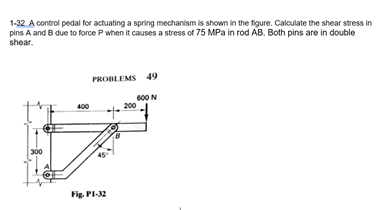
1-32 A control pedal for actuating a spring mechanism is shown in the figure. Calculate the shear stress in pins A and B due to force P when it causes a stress of 75 MPa in rod AB. Both pins are in double shear.
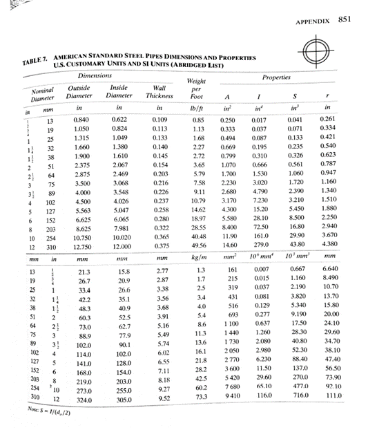
Diameter of the Pin attached in the photo of the table provided below.
Transcribed Image Text: 1-32 A control pedal for actuating a spring mechanism is shown in the figure. Calculate the shear stress in
pins A and B due to force Pwhen it causes a stress of 75 MPa in rod AB. Both pins are in double
shear.
PROBLEMS 49
600 N
200
400
300
Fig. PI-32
Transcribed Image Text: TABLE 7. AMERICAN STANDARD STEEL PIPES DIMENSIONS AND PROPERTIES
APPENDIX
851
U.S. CUSTOMARY UNITS AND SI UNITS (ABRIDGED LIST)
Dimensions
Properties
Weight
Outside
Inside
Wall
Nominal
Diameter
per
Foot
Diameter
Diameter
Thickness
in
in
in?
in
in
in
Ib/ft
in
in
0.840
0.622
0.109
0.85
0.250
0.261
0.017
0.037
13
0.041
19
1.050
0.824
0.113
1.13
0.333
0.071
0.334
25
1.315
1.049
0.133
1.68
0.494
0.087
0.133
0.421
1.660
1.380
0.140
2.27
0.669
0.195
0.235
0.540
1!
32
38
1.900
1.610
0.145
2.72
0.799
0.310
0.326
0.623
51
2.375
2.067
0.154
3.65
1.070
0.666
0.561
0.787
2
2.469
3.068
2!
2.875
0.203
5.79
1.700
1.530
1.060
0.947
64
75
3.500
0.216
7.58
2.230
3.020
1.720
1.160
3
2.390
3.210
5.450
89
4.000
3.548
0.226
9.11
2.680
4.790
1.340
3
4.026
0.237
10.79
3.170
7.230
1.510
4.500
5.563
6.625
102
5.047
0.258
14.62
4.300
15.20
1.880
127
2.250
0.280
0.322
6.
152
6.065
18.97
5.580
28.10
8.500
203
8.625
7.981
28.55
8.400
72.50
16.80
2.940
254
10.750
10.020
0.365
40.48
11.90
161.0
29.90
3.670
10
12
310
12.750
12.000
0.375
49.56
14.60
279.0
43.80
4.380
kg/m
10° mm
10' mm'
in
mm
1.3
0.007
0.667
6.640
13
21.3
15.8
2.77
161
19
26.7
20.9
2.87
1.7
215
0.015
1.160
8.490
25
26.6
3.38
2.5
319
0.037
2.190
10.70
1
1.
1
33.4
32
42.2
35.1
3.56
3.4
431
0.081
3.820
13.70
4.0
516
0.129
5.340
15.80
38
48.3
40.9
3.68
51
3.91
5.4
693
0.277
9.190
20.00
2
60.3
52.5
64
2
62.7
5.16
8.6
1 100
0.637
17.50
24.10
73.0
75
5.49
11.3
1440
1.260
28.30
29.60
3
88.9
77.9
89
3!
5.74
13.6
1730
2.080
40.80
34.70
102.0
90.1
2050
2.980
52.30
38.10
6.02
6.55
102
4
114.0
102.0
16.1
127
21.8
2770
6.230
88.40
47.40
141.0
128.0
28.2
3 600
11.50
137.0
56.50
152
203
6.
168.0
154.0
7.11
5 420
7 680
8
8.18
42.5
29.60
270.0
73.90
219.0
203.0
254
10
9.27
60.2
65.10
0ר47
92.10
273.0
255.0
310
12
9.52
73.3
9410
116.0
716.0
111.0
324.0
305.0
Note: S- 1/(4,/2)
Branch of science that deals with the stationary and moving bodies under the influence of forces.
Expert Solution
This question has been solved!
Explore an expertly crafted, step-by-step solution for a thorough understanding of key concepts.
This is a popular solution!
Trending now
This is a popular solution!
Step by step
Solved in 5 steps with 1 images