
Mechanics of Materials (MindTap Course List)
9th Edition
ISBN: 9781337093347
Author: Barry J. Goodno, James M. Gere
Publisher: Cengage Learning
expand_more
expand_more
format_list_bulleted
Concept explainers
Videos
Textbook Question
Chapter 8, Problem 8.5.28P
A crank arm consists of a solid segment of length bxand diameter rf, a segment of length bltand a segment of length byas shown in the figure. Two loads P act as shown: one parallel to — vand another parallel to —y. Each load P equals 1.2 kN. The crankshaft dimensions are A] = 75 mm, fr> = 125 mm, and b3= 35 mm. The diameter of the upper shaft isd = 22 mm,
(a) Determine the maximum tensile, compressive, and shear stresses at point A, which is located on the surface of the shaft at the z axis.
(b) Determine the maximum tensile, compressive, and shear stresses at point B, which is located on the surface of the shaft at the y axis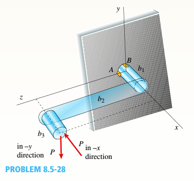
Expert Solution & Answer

Trending nowThis is a popular solution!

Chapter 8 Solutions
Mechanics of Materials (MindTap Course List)
Ch. 8 - A spherical balloon is filled with a gas. The...Ch. 8 - A spherical balloon with an outer diameter of 500...Ch. 8 - A large spherical tank (see figure) contains gas...Ch. 8 - Solve the preceding problem if the internal...Ch. 8 - A hemispherical window (or viewport) in a...Ch. 8 - A rubber ball (sec figure) is inflated to a...Ch. 8 - (a) Solve part (a) of the preceding problem if the...Ch. 8 - A spherical steel pressure vessel (diameter 500...Ch. 8 - A spherical tank of diameter 48 in. and wall...Ch. 8 - Solve the preceding problem for the following...
Ch. 8 - A spherical stainless-steel tank having a diameter...Ch. 8 - Solve the preceding problem if the diameter is 480...Ch. 8 - : A hollow, pressurized sphere having a radius r =...Ch. 8 - A fire extinguisher tank is designed for an...Ch. 8 - Prob. 8.3.2PCh. 8 - A scuba t a n k (see fig ure) i s bci ng d e...Ch. 8 - A tall standpipc with an open top (see figure) has...Ch. 8 - An inflatable structure used by a traveling circus...Ch. 8 - A thin-walled cylindrical pressure vessel of a...Ch. 8 - A strain gage is installed in the longitudinal...Ch. 8 - A circular cylindrical steel tank (see figure)...Ch. 8 - A cylinder filled with oil is under pressure from...Ch. 8 - Solve the preceding problem if F =90 mm, F = 42...Ch. 8 - A standpipe in a water-supply system (see figure)...Ch. 8 - A cylindrical tank with hemispherical heads is...Ch. 8 - : A cylindrical tank with diameter d = 18 in, is...Ch. 8 - A pressurized steel tank is constructed with a...Ch. 8 - Solve the preceding problem for a welded Tank with...Ch. 8 - A wood beam with a cross section 4 x 6 in. is...Ch. 8 - Prob. 8.4.2PCh. 8 - A simply supported beam is subjected to two point...Ch. 8 - A cantilever beam with a width h = 100 mm and...Ch. 8 - A beam with a width h = 6 in. and depth h = 8 in....Ch. 8 - Beam ABC with an overhang BC is subjected to a...Ch. 8 - A cantilever beam(Z, = 6 ft) with a rectangular...Ch. 8 - Solve the preceding problem for the following...Ch. 8 - A simple beam with a rectangular cross section...Ch. 8 - An overhanging beam ABC has a guided support at A,...Ch. 8 - Solve the preceding problem if the stress and...Ch. 8 - A cantilever wood beam with a width b = 100 mm and...Ch. 8 - . A cantilever beam (width b = 3 in. and depth h =...Ch. 8 - A beam with a wide-flange cross section (see...Ch. 8 - A beam with a wide-flange cross section (see...Ch. 8 - A W 200 x 41.7 wide-flange beam (see Table F-l(b),...Ch. 8 - A W 12 x 35 steel beam is fixed at A. The beam has...Ch. 8 - A W 360 x 79 steel beam is fixed at A. The beam...Ch. 8 - A W 12 X 14 wide-flange beam (see Table F-l(a),...Ch. 8 - A cantilever beam with a T-section is loaded by an...Ch. 8 - Beam A BCD has a sliding support at A, roller...Ch. 8 - , Solve the preceding problem using the numerical...Ch. 8 - A W 12 x 35 steel cantilever beam is subjected to...Ch. 8 - A W 310 x 52 steel beam is subjected to a point...Ch. 8 - A solid circular bar is fixed at point A. The bar...Ch. 8 - A cantilever beam with a width h = 100 mm and...Ch. 8 - Solve the preceding problem using the following...Ch. 8 - A cylindrical tank subjected to internal...Ch. 8 - A cylindrical pressure vessel having a radius r =...Ch. 8 - A pressurized cylindrical tank with flat ends is...Ch. 8 - A cylindrical pressure vessel with flat ends is...Ch. 8 - The tensional pendulum shown in the figure...Ch. 8 - The hollow drill pipe for an oil well (sec figure)...Ch. 8 - Solve the preceding problem if the diameter is 480...Ch. 8 - . A segment of a generator shaft with a hollow...Ch. 8 - A post having a hollow, circular cross section...Ch. 8 - A sign is supported by a pole of hollow circular...Ch. 8 - A sign is supported by a pipe (see figure) having...Ch. 8 - A traffic light and signal pole is subjected to...Ch. 8 - Repeat the preceding problem but now find the...Ch. 8 - A bracket ABCD having a hollow circular cross...Ch. 8 - A gondola on a ski lift is supported by two bent...Ch. 8 - Beam A BCD has a sliding support at A, roller...Ch. 8 - A double-decker bicycle rack made up of square...Ch. 8 - A semicircular bar AB lying in a horizontal plane...Ch. 8 - Repeat Problem 8.5-22 but replace the square tube...Ch. 8 - An L-shaped bracket lying in a horizontal plane...Ch. 8 - A horizontal bracket ABC consists of two...Ch. 8 - , An arm A BC lying in a horizontal plane and...Ch. 8 - A crank arm consists of a solid segment of length...Ch. 8 - A moveable steel stand supports an automobile...Ch. 8 - A mountain bike rider going uphill applies a force...Ch. 8 - Determine the maximum tensile, compressive, and...Ch. 8 - Prob. 8.5.32PCh. 8 - A plumber's valve wrench is used to replace valves...Ch. 8 - A compound beam ABCD has a cable with force P...Ch. 8 - A steel hanger bracket ABCD has a solid, circular...
Knowledge Booster


Learn more about
Need a deep-dive on the concept behind this application? Look no further. Learn more about this topic, mechanical-engineering and related others by exploring similar questions and additional content below.Similar questions
- A cable and pulley system in the figure part a supports a cage of a mass 300 kg at B. Assume that this includes the mass of the cables as well. The thickness or each of the three steel pulleys is t = 40 mm. The pin diameters are dPA= 25 mm, dB= 30 mm. and dc= 22 mm (see figure part a and part b). (a) Find expressions for the resultant forces acting on the pulleys at A, B. and C in terms of cubic tension T. (b) What is the maximum weight W that can be added to the cage at B based on the following allowable stresses? Shear stress in the pins is 50 MPa; bearing stress between the pin and the pulley is 110 MPa.arrow_forwardB cams AB and CDE are connected using rigid link DB with hinges (or moment releases) at ends D and B (see figure a). Beam AB is fixed at joint A and beam CDE is pin-supported at joint E. Load P = 150 lb is applied at C\ Calculate the deflections of joints B and joint C Assume L = 9 ft and EI = 127,000 kip-in2. Repeat part (a) if rigid link DB is replaced by a linear spring with k = 20 kips/in (see figure b).arrow_forwardRepeat Problem 11.3-9. Use two C 150 × 12.2 steel shapes and assume that E = 205 GPa and L = 6 m.arrow_forward
- A T-frame structure is torn posed of a prismatic beam ABC and a nonprismatic column DBF. The beam and the column have a pin support at .A and D, respectively. Both members are connected with a pin at B. The lengths and properties of the members are shown in the figure. Find the vertical displacement of the column at points F and B. Plot axial force (AFD) and axial displacement (ADD) diagrams For column DBF.arrow_forwardRepeat 1.3-9 but use the method of sections go find member forces in AC and BD.arrow_forwardRepeat Problem 6.4-14 but use the configuration of channel shapes and loading shown in the figure. Use P = 250 N.arrow_forward
- A seesaw weighing 3 lb/ft of length is occupied by two children, each weighing 90 lb (see figure). The center of gravity of each child is 8 ft from the fulcrum. The board is 19 ft long, 8 in. wide, and 1.5 in. thick. What is the maximum bending stress in the board?arrow_forwardA cable and pulley system at D is used to bring a 230-lcg pole (ACB) to a vertical position, as shown in the Figure part a. The cable has tensile force T and is attached at C. The length L of the pole is 6.0m, the outer diameter is d = 140 mm. and the wall thickness is t = 12 mm. The pole pivots about a pin at A in figure part b. The allowable shear stress in the pin is 60 MPa and the allowable bearing stress is 90 MPa. Find the minimum diameter of the pin at A in order to support the weight of the pole in the position shown in the figure part a.arrow_forwardCompare the angle of twist 1 for a thin-walled circular tube (see figure) calculated from the approximate theory for thin-walled bars with the angle of twist 2 calculated from the exact theory of torsion for circular bars, Express the ratio 12terms of the non-dimensional ratio ß = r/t. Calculate the ratio of angles of twist for ß = 5, 10, and 20. What conclusion about the accuracy of the approximate theory do you draw from these results?arrow_forward
- A stepped shaft ACE is held against rotation at ends A and B and subjected to a torque T0acting at section C(see figure). The two segments of the shaft (AC and CB) have diameters dAand dg, respectively, and polar moments of inertia IpAand IpBrespectively. The shaft has length L and segment AC has length a. For what ratio a/L will the maximum shear stresses be the same in both segments of the shaft? For what ratio a/L will the internal torques be the same in both segments of the shaft?arrow_forwardRepeat Problem 10.4-41 for the loading shown in the figure.arrow_forwardTwo rigid bars are connected to each other by two linearly elastic springs. Before loads are applied, the lengths or the springs are such, that the bars are parallel and the springs are without stress. (a) Derive a formula for the displacement E4at point 4 when the load P is applied at joint 3 and moment PL is applied at joint 1. as shown in the figure part a. (Assume that the bars rotate through very small angles under the action of load P.) (b) Repeat part (a) if a rotational spring, kr= kL2, is now added at joint 6. What is the ratio of the deflection d4 in the figure part a to that in the figure part b ?arrow_forward
arrow_back_ios
SEE MORE QUESTIONS
arrow_forward_ios
Recommended textbooks for you
 Mechanics of Materials (MindTap Course List)Mechanical EngineeringISBN:9781337093347Author:Barry J. Goodno, James M. GerePublisher:Cengage Learning
Mechanics of Materials (MindTap Course List)
Mechanical Engineering
ISBN:9781337093347
Author:Barry J. Goodno, James M. Gere
Publisher:Cengage Learning
EVERYTHING on Axial Loading Normal Stress in 10 MINUTES - Mechanics of Materials; Author: Less Boring Lectures;https://www.youtube.com/watch?v=jQ-fNqZWrNg;License: Standard YouTube License, CC-BY