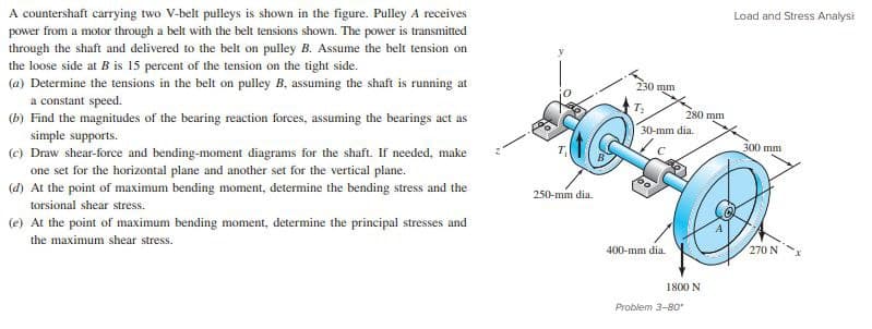
A countershaft carrying two V-belt pulleys is shown in the figure. Pulley A receives power from a motor through a belt with the belt tensions shown. The power is transmitted through the shaft and delivered to the belt on pulley B. Assume the belt tension on the loose side at B is 15 percent of the tension on the tight side. (a) Determine the tensions in the belt on pulley B, assuming the shaft is running at a constant speed. (b) Find the magnitudes of the bearing reaction forces, assuming the bearings act as simple supports. (c) Draw shear-force and bending-moment diagrams for the shaft. If needed, make one set for the horizontal plane and another set for the vertical plane. (d) At the point of maximum bending moment, determine the bending stress and the torsional shear stress. (e) At the point of maximum bending moment, determine the principal stresses and the maximum shear stress.
A countershaft carrying two V-belt pulleys is shown in the figure. Pulley A receives power from a motor through a belt with the belt tensions shown. The power is transmitted through the shaft and delivered to the belt on pulley B. Assume the belt tension on the loose side at B is 15 percent of the tension on the tight side. (a) Determine the tensions in the belt on pulley B, assuming the shaft is running at a constant speed. (b) Find the magnitudes of the bearing reaction forces, assuming the bearings act as simple supports. (c) Draw shear-force and bending-moment diagrams for the shaft. If needed, make one set for the horizontal plane and another set for the vertical plane. (d) At the point of maximum bending moment, determine the bending stress and the torsional shear stress. (e) At the point of maximum bending moment, determine the principal stresses and the maximum shear stress.

Mechanics of Materials (MindTap Course List)
9th Edition
ISBN:9781337093347
Author:Barry J. Goodno, James M. Gere
Publisher:Barry J. Goodno, James M. Gere
Chapter1: Tension, Compression, And Shear
Section: Chapter Questions
Problem 1.8.5P: The Force in the brake cable of the V-brake system shown in the figure is T — 45 lb. The pivot pin...

Related questions
Question
I need the answer as soon as possible
Transcribed Image Text:A countershaft carrying two V-belt pulleys is shown in the figure. Pulley A receives
power from a motor through a belt with the belt tensions shown. The power is transmitted
through the shaft and delivered to the belt on pulley B. Assume the belt tension on
the loose side at B is 15 percent of the tension on the tight side.
(a) Determine the tensions in the belt on pulley B, assuming the shaft is running at
a constant speed.
(b) Find the magnitudes of the bearing reaction forces, assuming the bearings act as
simple supports.
(c) Draw shear-force and bending-moment diagrams for the shaft. If needed, make
Load and Stress Analysi
230 mm
T:
280 mm
30-mm dia.
300 mm
one set for the horizontal plane and another set for the vertical plane.
(d) At the point of maximum bending moment, determine the bending stress and the
250-mm dia.
torsional shear stress.
(e) At the point of maximum bending moment, determine the principal stresses and
the maximum shear stress.
400-mm dia.
270 N
1800 N
Problem 3-80
Expert Solution
This question has been solved!
Explore an expertly crafted, step-by-step solution for a thorough understanding of key concepts.

This is a popular solution!

Trending now
This is a popular solution!

Step by step
Solved in 5 steps with 5 images

Knowledge Booster


Learn more about
Need a deep-dive on the concept behind this application? Look no further. Learn more about this topic, mechanical-engineering and related others by exploring similar questions and additional content below.Recommended textbooks for you
Mechanics of Materials (MindTap Course List)
Mechanical Engineering
ISBN:
9781337093347
Author:
Barry J. Goodno, James M. Gere
Publisher:
Cengage Learning
Mechanics of Materials (MindTap Course List)
Mechanical Engineering
ISBN:
9781337093347
Author:
Barry J. Goodno, James M. Gere
Publisher:
Cengage Learning