1-A solid axial member which is made from three parts with different materials (sections 1 and 3) is loaded and supported as shown in the Figure 1. Segments (1) has a diameter of 30 segment (2) has a diameter of 20 mm and segment (3) has a diameter of 25 mm. For the El modulus of segments please follow the table 1. (1) 1.1 m B P = 40 kN 1.3 m (2) C P = 10 kN 0.7 m
1-A solid axial member which is made from three parts with different materials (sections 1 and 3) is loaded and supported as shown in the Figure 1. Segments (1) has a diameter of 30 segment (2) has a diameter of 20 mm and segment (3) has a diameter of 25 mm. For the El modulus of segments please follow the table 1. (1) 1.1 m B P = 40 kN 1.3 m (2) C P = 10 kN 0.7 m

Mechanics of Materials (MindTap Course List)
9th Edition
ISBN:9781337093347
Author:Barry J. Goodno, James M. Gere
Publisher:Barry J. Goodno, James M. Gere
Chapter2: Axially Loaded Members
Section: Chapter Questions
Problem 2.4.6P: Three prismatic bars, two of material A and one of material B. transmit a tensile load P (see...

Related questions

Question
100%
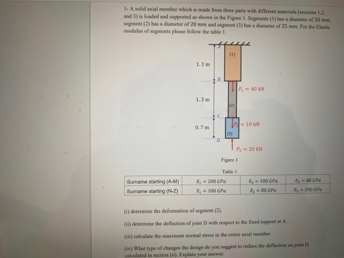
Transcribed Image Text:1- A solid axial member which is made from three parts with different materials (sections 1,2,
and 3) is loaded and supported as shown in the Figure 1. Segments (1) has a diameter of 30 mm,
segment (2) has a diameter of 20 mm and segment (3) has a diameter of 25 mm. For the Elastic
modulus of segments please follow the table 1.
(1)
1.1 m
B
P = 40 kN
1.3 m
(2)
P= 10 kN
0.7 m
(3)
P = 20 kN
Figure 1
Table 1
Surname starting (A-M)
E, = 200 GPa
E2 = 100 GPa
E = 80 GPa
Surname starting (N-Z)
E, = 100 GPa
E = 80 GPa
E = 200 GPa
(i) determine the deformation of segment (2).
(ii) determine the deflection of joint D with respect to the fixed support at A.
(iii) calculate the maximum normal stress in the entire axial member.
(iv) What type of changes the design do you suggest to reduce the deflection on joint D
calculated in section (ii). Explain your answer.
Expert Solution
This question has been solved!
Explore an expertly crafted, step-by-step solution for a thorough understanding of key concepts.

This is a popular solution!

Trending now
This is a popular solution!

Step by step
Solved in 2 steps with 1 images

Follow-up Questions
Read through expert solutions to related follow-up questions below.
Knowledge Booster


Learn more about
Need a deep-dive on the concept behind this application? Look no further. Learn more about this topic, mechanical-engineering and related others by exploring similar questions and additional content below.Recommended textbooks for you
Mechanics of Materials (MindTap Course List)
Mechanical Engineering
ISBN:
9781337093347
Author:
Barry J. Goodno, James M. Gere
Publisher:
Cengage Learning
Mechanics of Materials (MindTap Course List)
Mechanical Engineering
ISBN:
9781337093347
Author:
Barry J. Goodno, James M. Gere
Publisher:
Cengage Learning