1. A coil with inductance and resistance of 1.0 mH and 2.0 2, respectively, is connected in series with a capacitor and a 120-V 5-kHz supply. Determine the value of capacitance that will cause the system to be in resonance and the current at the resonance frequency. 2. Determine the parameters of a series RLC circuit that will resonate at 10 kHz, have a bandwidth of 1 kHz, and draw 15.3 W from a 200-V generator operating at the resonance frequency of the circuit.
1. A coil with inductance and resistance of 1.0 mH and 2.0 2, respectively, is connected in series with a capacitor and a 120-V 5-kHz supply. Determine the value of capacitance that will cause the system to be in resonance and the current at the resonance frequency. 2. Determine the parameters of a series RLC circuit that will resonate at 10 kHz, have a bandwidth of 1 kHz, and draw 15.3 W from a 200-V generator operating at the resonance frequency of the circuit.

Introductory Circuit Analysis (13th Edition)
13th Edition
ISBN:9780133923605
Author:Robert L. Boylestad
Publisher:Robert L. Boylestad
Chapter1: Introduction
Section: Chapter Questions
Problem 1P: Visit your local library (at school or home) and describe the extent to which it provides literature...

Related questions
Question
C. Answer 1 and 2
Transcribed Image Text:TEST YOURSELF
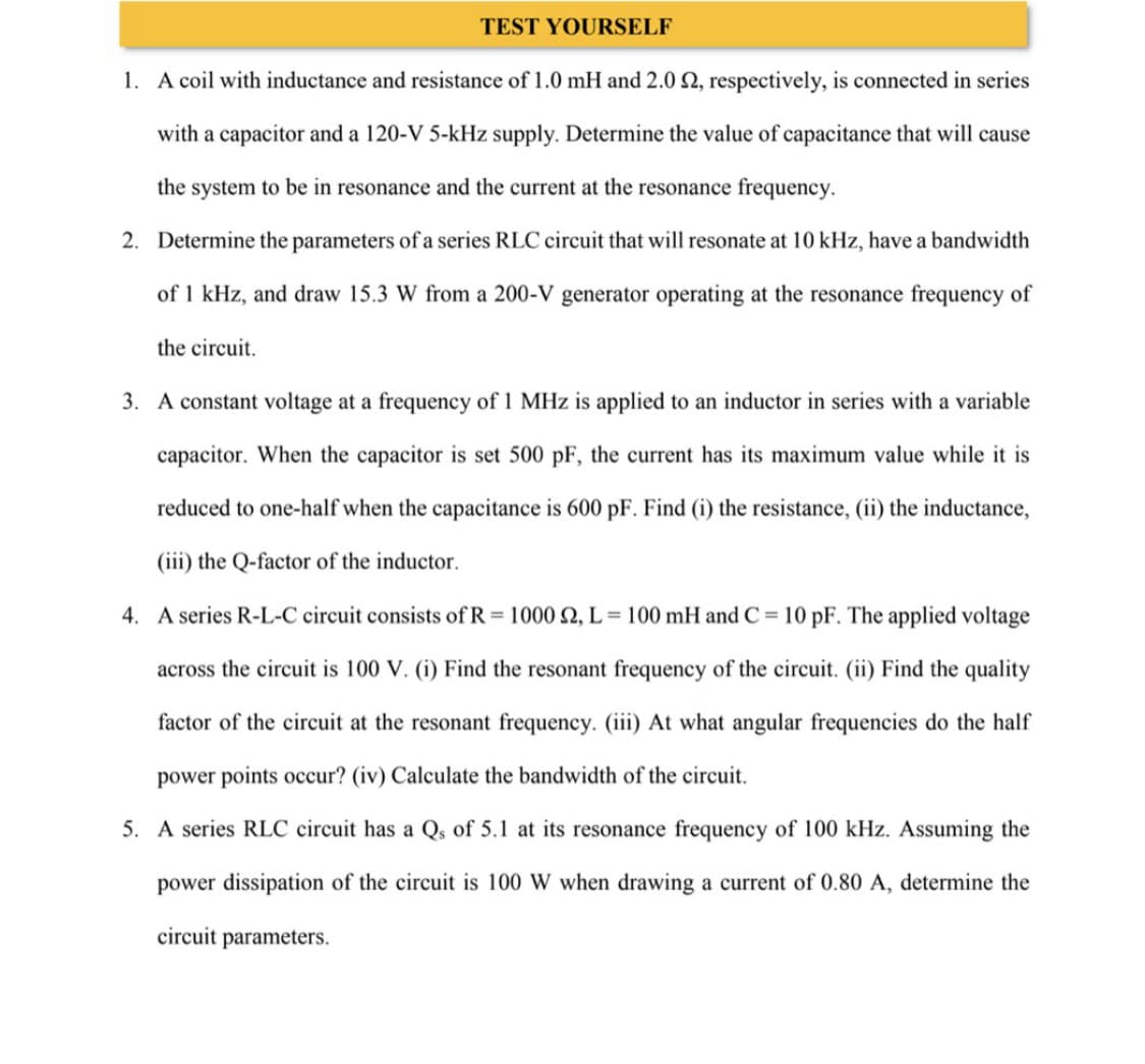
1. A coil with inductance and resistance of 1.0 mH and 2.0 2, respectively, is connected in series
with a capacitor and a 120-V 5-kHz supply. Determine the value of capacitance that will cause
the system to be in resonance and the current at the resonance frequency.
2. Determine the parameters of a series RLC circuit that will resonate at 10 kHz, have a bandwidth
of 1 kHz, and draw 15.3 W from a 200-V generator operating at the resonance frequency of
the circuit.
3. A constant voltage at a frequency of 1 MHz is applied to an inductor in series with a variable
capacitor. When the capacitor is set 500 pF, the current has its maximum value while it is
reduced to one-half when the capacitance is 600 pF. Find (i) the resistance, (ii) the inductance,
(iii) the Q-factor of the inductor.
4. A series R-L-C circuit consists of R = 1000 2, L=100 mH and C= 10 pF. The applied voltage
across the circuit is 100 V. (i) Find the resonant frequency of the circuit. (ii) Find the quality
factor of the circuit at the resonant frequency. (iii) At what angular frequencies do the half
power points occur? (iv) Calculate the bandwidth of the circuit.
5. A series RLC circuit has a Qs of 5.1 at its resonance frequency of 100 kHz. Assuming the
power dissipation of the circuit is 100 W when drawing a current of 0.80 A, determine the
circuit parameters.
Expert Solution
This question has been solved!
Explore an expertly crafted, step-by-step solution for a thorough understanding of key concepts.

This is a popular solution!

Trending now
This is a popular solution!

Step by step
Solved in 5 steps with 5 images

Knowledge Booster


Learn more about
Need a deep-dive on the concept behind this application? Look no further. Learn more about this topic, electrical-engineering and related others by exploring similar questions and additional content below.Recommended textbooks for you
Introductory Circuit Analysis (13th Edition)
Electrical Engineering
ISBN:
9780133923605
Author:
Robert L. Boylestad
Publisher:
PEARSON

Delmar's Standard Textbook Of Electricity
Electrical Engineering
ISBN:
9781337900348
Author:
Stephen L. Herman
Publisher:
Cengage Learning

Programmable Logic Controllers
Electrical Engineering
ISBN:
9780073373843
Author:
Frank D. Petruzella
Publisher:
McGraw-Hill Education
Introductory Circuit Analysis (13th Edition)
Electrical Engineering
ISBN:
9780133923605
Author:
Robert L. Boylestad
Publisher:
PEARSON
Delmar's Standard Textbook Of Electricity
Electrical Engineering
ISBN:
9781337900348
Author:
Stephen L. Herman
Publisher:
Cengage Learning
Programmable Logic Controllers
Electrical Engineering
ISBN:
9780073373843
Author:
Frank D. Petruzella
Publisher:
McGraw-Hill Education

Fundamentals of Electric Circuits
Electrical Engineering
ISBN:
9780078028229
Author:
Charles K Alexander, Matthew Sadiku
Publisher:
McGraw-Hill Education

Electric Circuits. (11th Edition)
Electrical Engineering
ISBN:
9780134746968
Author:
James W. Nilsson, Susan Riedel
Publisher:
PEARSON

Engineering Electromagnetics
Electrical Engineering
ISBN:
9780078028151
Author:
Hayt, William H. (william Hart), Jr, BUCK, John A.
Publisher:
Mcgraw-hill Education,