A generator having H = 6.0 MJ /MVA is delivering power of 1.0 per unit to an infinite bus through a purely reactive network when the occurrence of a fault reduces the generator output power to zero. The maximum power that could be delivered is 2.5 per unit. When the fault is cleared, the original network conditions again exist. Calculate: a) The critical clearing angle.
A generator having H = 6.0 MJ /MVA is delivering power of 1.0 per unit to an infinite bus through a purely reactive network when the occurrence of a fault reduces the generator output power to zero. The maximum power that could be delivered is 2.5 per unit. When the fault is cleared, the original network conditions again exist. Calculate: a) The critical clearing angle.

Power System Analysis and Design (MindTap Course List)
6th Edition
ISBN:9781305632134
Author:J. Duncan Glover, Thomas Overbye, Mulukutla S. Sarma
Publisher:J. Duncan Glover, Thomas Overbye, Mulukutla S. Sarma
Chapter7: Symmetrical Faults
Section: Chapter Questions
Problem 7.34P

Related questions
Question
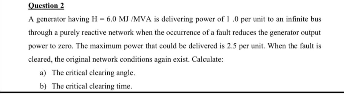
Transcribed Image Text:Question 2
A generator having H = 6.0 MJ /MVA is delivering power of 1 .0 per unit to an infinite bus
through a purely reactive network when the occurrence of a fault reduces the generator output
power to zero. The maximum power that could be delivered is 2.5 per unit. When the fault is
cleared, the original network conditions again exist. Calculate:
a) The critical clearing angle.
b) The critical clearing time.
Expert Solution
This question has been solved!
Explore an expertly crafted, step-by-step solution for a thorough understanding of key concepts.

This is a popular solution!

Trending now
This is a popular solution!

Step by step
Solved in 3 steps with 3 images

Knowledge Booster


Learn more about
Need a deep-dive on the concept behind this application? Look no further. Learn more about this topic, electrical-engineering and related others by exploring similar questions and additional content below.Recommended textbooks for you
Power System Analysis and Design (MindTap Course …
Electrical Engineering
ISBN:
9781305632134
Author:
J. Duncan Glover, Thomas Overbye, Mulukutla S. Sarma
Publisher:
Cengage Learning
Power System Analysis and Design (MindTap Course …
Electrical Engineering
ISBN:
9781305632134
Author:
J. Duncan Glover, Thomas Overbye, Mulukutla S. Sarma
Publisher:
Cengage Learning