1. A plate is subjected to a couple Fd, with d= 20cm , as shown below left. Verify that the couple can be moved to the position shown below right, and the effect on the plate is the same, by showing that the moment about point o in both cases is М--20F. 30 cm 20 cm, 100 cm 20 cm 100 cm F F )cm 100 cm 100 cm
1. A plate is subjected to a couple Fd, with d= 20cm , as shown below left. Verify that the couple can be moved to the position shown below right, and the effect on the plate is the same, by showing that the moment about point o in both cases is М--20F. 30 cm 20 cm, 100 cm 20 cm 100 cm F F )cm 100 cm 100 cm

International Edition---engineering Mechanics: Statics, 4th Edition
4th Edition
ISBN:9781305501607
Author:Andrew Pytel And Jaan Kiusalaas
Publisher:Andrew Pytel And Jaan Kiusalaas
Chapter7: Dry Friction
Section: Chapter Questions
Problem 7.11P: Solve Prob. 7.10 assuming that the pick-up truck has front-wheel drive.

Related questions
Question
Transcribed Image Text:break. The mrore sophisticateu analysis carried out in the following Chapters is
necessary to deal with this and many other questions of material response.
2.3.4
Problems
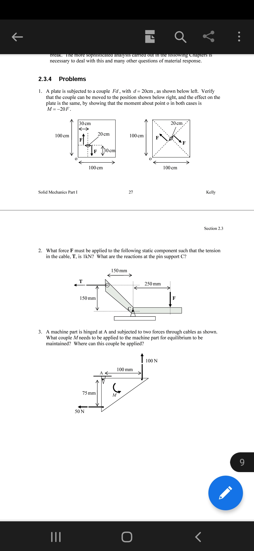
1. A plate is subjected to a couple Fd, with d= 20cm , as shown below left. Verify
that the couple can be moved to the position shown below right, and the effect on the
plate is the same, by showing that the moment about point o in both cases is
М -- 20 F.
30 cm
20 cm
100 cm
20 cm
100 cm
F
cm
100 cm
100 cm
Solid Mechanics Part I
27
Kelly
Section 2.3
2. What force F must be applied to the following static component such that the tension
in the cable, T, is 1kN? What are the reactions at the pin support C?
150 mm
T
250 mm
150 mm
F
3. A machine part is hinged at A and subjected to two forces through cables as shown.
What couple M needs to be applied to the machine part for equilibrium to be
maintained? Where can this couple be applied?
100 N
100 mm
75 mm
M
50 N
9.
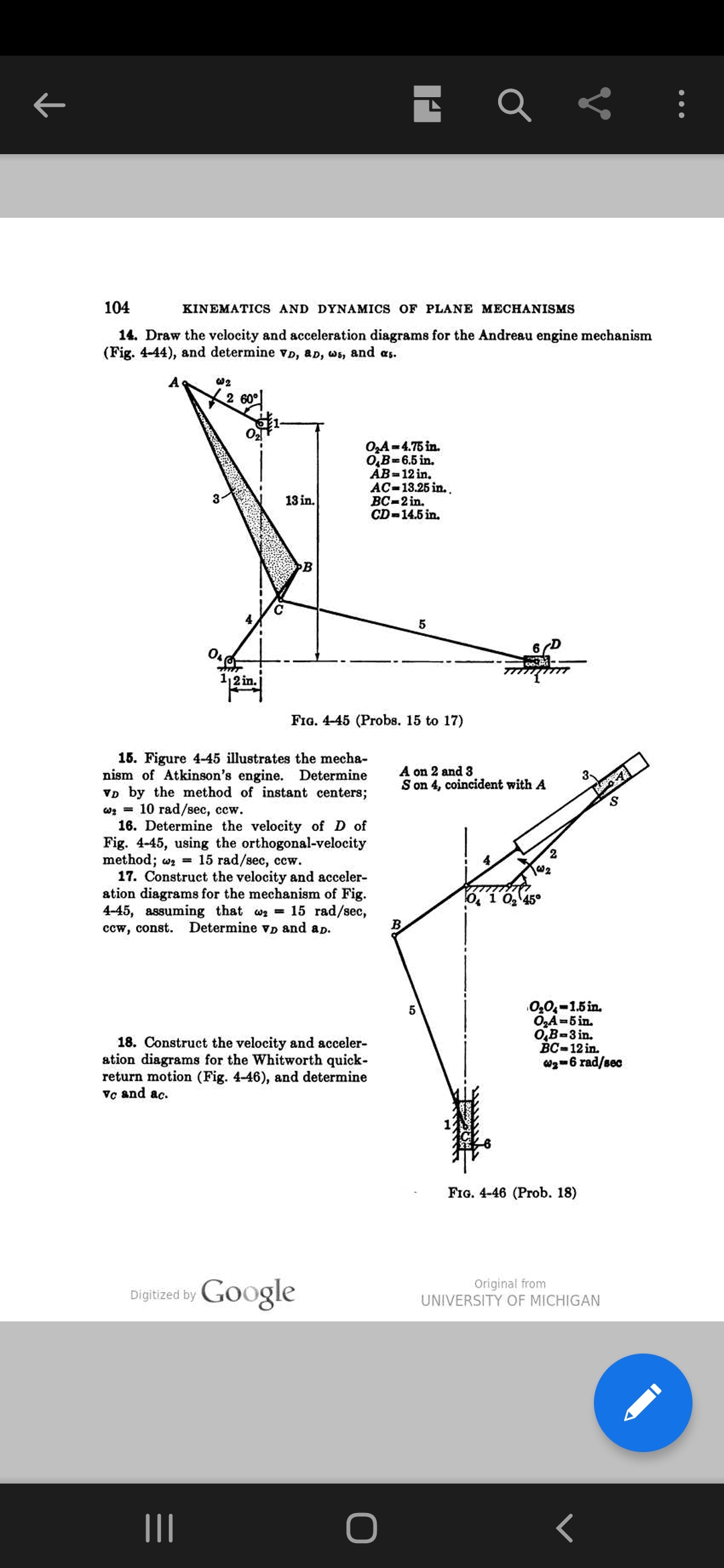
Transcribed Image Text:104
KINEMATICS AND DYNAMICS OF PLANE MECHANISMS
14. Draw the velocity and acceleration diagrams for the Andreau engine mechanism
(Fig. 4-44), and determine vD, aD, ws, and as.
A
w2
2 60°
O,A=4.75 in.
O,B=6.5 in.
AB=12 in.
AC-13.25 in. .
ВС-2 in.
CD-14.5 in.
13 in.
B
5
6D
12 in.
FIG. 4-45 (Probs. 15 to 17)
15. Figure 4-45 illustrates the mecha-
nism of Atkinson's engine. Determine
VD by the method of instant centers;
оз 3 10 гаd/sec, ссw.
16. Determine the velocity of D of
Fig. 4-45, using the orthogonal-velocity
method; wz = 15 rad/sec, ccw.
17. Construct the velocity and acceler-
ation diagrams for the mechanism of Fig.
4-45, assuming that wa 15 rad/sec,
ccw, const.
A on 2 and 3
S on 4, coincident with A
2.
O, 1 0, 45°
Determine vD and ap.
18. Construct the velocity and acceler-
ation diagrams for the Whitworth quick-
return motion (Fig. 4-46), and determine
Vc and ac.
0,0,-1.5 in.
O,A-5 in.
0,B-3 in.
Вс-12 in.
Wg-6 rad/sec
FIG. 4-46 (Prob. 18)
Digitized by Google
Original from
UNIVERSITY OF MICHIGAN
Expert Solution
This question has been solved!
Explore an expertly crafted, step-by-step solution for a thorough understanding of key concepts.

Step by step
Solved in 3 steps with 2 images

Knowledge Booster


Learn more about
Need a deep-dive on the concept behind this application? Look no further. Learn more about this topic, mechanical-engineering and related others by exploring similar questions and additional content below.Recommended textbooks for you
International Edition---engineering Mechanics: St…
Mechanical Engineering
ISBN:
9781305501607
Author:
Andrew Pytel And Jaan Kiusalaas
Publisher:
CENGAGE L
International Edition---engineering Mechanics: St…
Mechanical Engineering
ISBN:
9781305501607
Author:
Andrew Pytel And Jaan Kiusalaas
Publisher:
CENGAGE L