1. Consider the circuit below +12V R1=12K R2 The light-dependent-resistor (LDR) R2 is 1M2 when itť's covered and 5002 when exposed to light. Leť's model the LED lamp chip as two diodes in series, each with a forward voltage of 5V, so that the total voltage across it, when on, is 10V Assume beta = 100, VBe,On=0.7 and VCE,SAT=0.6V a. Suppose R2 is exposed to light and we assume the BJT is F.A. and the LED's are ON. Verify if our assumptions are correct. If the verification fails, what is a more appropriate state for the BJT and the LEDS? b. Suppose R2 is covered. Determine and verify the state of the BJT and the diodes.
1. Consider the circuit below +12V R1=12K R2 The light-dependent-resistor (LDR) R2 is 1M2 when itť's covered and 5002 when exposed to light. Leť's model the LED lamp chip as two diodes in series, each with a forward voltage of 5V, so that the total voltage across it, when on, is 10V Assume beta = 100, VBe,On=0.7 and VCE,SAT=0.6V a. Suppose R2 is exposed to light and we assume the BJT is F.A. and the LED's are ON. Verify if our assumptions are correct. If the verification fails, what is a more appropriate state for the BJT and the LEDS? b. Suppose R2 is covered. Determine and verify the state of the BJT and the diodes.

Introductory Circuit Analysis (13th Edition)
13th Edition
ISBN:9780133923605
Author:Robert L. Boylestad
Publisher:Robert L. Boylestad
Chapter1: Introduction
Section: Chapter Questions
Problem 1P: Visit your local library (at school or home) and describe the extent to which it provides literature...

Related questions

Question
#1. will give high rating if answers are correct
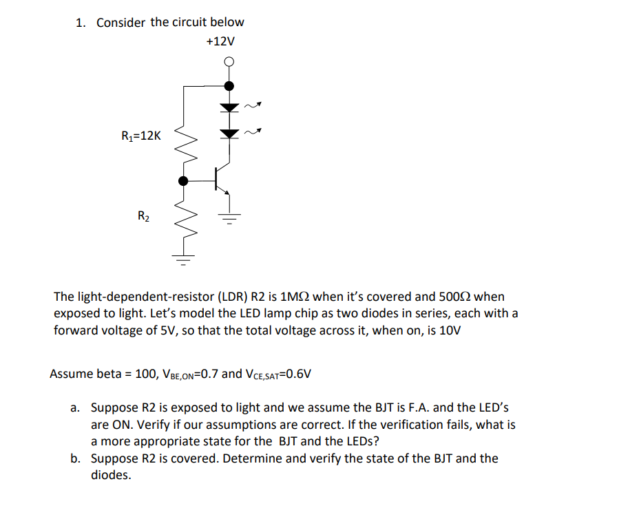
Transcribed Image Text:1. Consider the circuit below
+12V
R1=12K
R2
The light-dependent-resistor (LDR) R2 is 1M2 when it's covered and 5002 when
exposed to light. Let's model the LED lamp chip as two diodes in series, each with a
forward voltage of 5V, so that the total voltage across it, when on, is 10V
Assume beta = 100, VBe,on=0.7 and VCe,SAT=0.6V
a. Suppose R2 is exposed to light and we assume the BJT is F.A. and the LED's
are ON. Verify if our assumptions are correct. If the verification fails, what is
a more appropriate state for the BJT and the LEDS?
b. Suppose R2 is covered. Determine and verify the state of the BJT and the
diodes.
Expert Solution
This question has been solved!
Explore an expertly crafted, step-by-step solution for a thorough understanding of key concepts.

Step by step
Solved in 3 steps with 3 images

Knowledge Booster


Learn more about
Need a deep-dive on the concept behind this application? Look no further. Learn more about this topic, electrical-engineering and related others by exploring similar questions and additional content below.Recommended textbooks for you
Introductory Circuit Analysis (13th Edition)
Electrical Engineering
ISBN:
9780133923605
Author:
Robert L. Boylestad
Publisher:
PEARSON

Delmar's Standard Textbook Of Electricity
Electrical Engineering
ISBN:
9781337900348
Author:
Stephen L. Herman
Publisher:
Cengage Learning

Programmable Logic Controllers
Electrical Engineering
ISBN:
9780073373843
Author:
Frank D. Petruzella
Publisher:
McGraw-Hill Education
Introductory Circuit Analysis (13th Edition)
Electrical Engineering
ISBN:
9780133923605
Author:
Robert L. Boylestad
Publisher:
PEARSON
Delmar's Standard Textbook Of Electricity
Electrical Engineering
ISBN:
9781337900348
Author:
Stephen L. Herman
Publisher:
Cengage Learning
Programmable Logic Controllers
Electrical Engineering
ISBN:
9780073373843
Author:
Frank D. Petruzella
Publisher:
McGraw-Hill Education

Fundamentals of Electric Circuits
Electrical Engineering
ISBN:
9780078028229
Author:
Charles K Alexander, Matthew Sadiku
Publisher:
McGraw-Hill Education

Electric Circuits. (11th Edition)
Electrical Engineering
ISBN:
9780134746968
Author:
James W. Nilsson, Susan Riedel
Publisher:
PEARSON

Engineering Electromagnetics
Electrical Engineering
ISBN:
9780078028151
Author:
Hayt, William H. (william Hart), Jr, BUCK, John A.
Publisher:
Mcgraw-hill Education,