1. Construct the circuit of JK flip flop by using SR flip. The circuit can be constructed by using the conversion method taught in class.
1. Construct the circuit of JK flip flop by using SR flip. The circuit can be constructed by using the conversion method taught in class.

Chapter22: Sequence Control
Section: Chapter Questions
Problem 6SQ: Draw a symbol for a solid-state logic element AND.

Related questions
Question
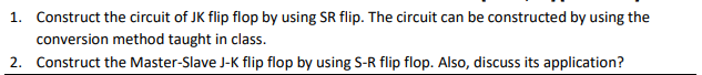
Transcribed Image Text:1. Construct the circuit of JK flip flop by using SR flip. The circuit can be constructed by using the
conversion method taught in class.
2. Construct the Master-Slave J-K flip flop by using S-R flip flop. Also, discuss its application?
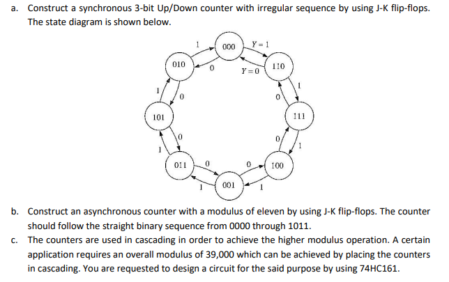
Transcribed Image Text:a. Construct a synchronous 3-bit Up/Down counter with irregular sequence by using J-K flip-flops.
The state diagram is shown below.
Y = 1
00
010
110
Y =0
101
111
0,
011
100
001
b. Construct an asynchronous counter with a modulus of eleven by using J-K flip-flops. The counter
should follow the straight binary sequence from 0000 through 1011.
c. The counters are used in cascading in order to achieve the higher modulus operation. A certain
application requires an overall modulus of 39,000 which can be achieved by placing the counters
in cascading. You are requested to design a circuit for the said purpose by using 74HC161.
Expert Solution
This question has been solved!
Explore an expertly crafted, step-by-step solution for a thorough understanding of key concepts.

This is a popular solution!

Trending now
This is a popular solution!

Step by step
Solved in 2 steps with 1 images

Knowledge Booster


Learn more about
Need a deep-dive on the concept behind this application? Look no further. Learn more about this topic, electrical-engineering and related others by exploring similar questions and additional content below.Recommended textbooks for you